Embedded systems design, Microchip PIC , Microcontroller , Electronics , Software , Computer , PC,Embedded Systems in Egypt , Microcontroller companies in Egypt , Microcontroller Tutorial for beginners, Microchip Microcontrollers tutorial , Microcontrollers made easy, Microcontroller DIY, DIY,embedded systems,embedded system , open source embedded software,list of embedded systems companies in Egypt, Quadcopter , Embedded Systems components in Egypt , Embedded Systems Components Stores in Egypt
Mturk Jobs
Mturk Jobs
Tank
Showing posts with label Arduino Bluetooth Module. Show all posts
Showing posts with label Arduino Bluetooth Module. Show all posts
This is a Smartphone Bluetooth controlled RGB Mood light lamp using Arduino and HC-06 Bluetooth Module.
This project is both easy and rewarding. Mood light is a nice project to make for your kids and family. It adds a touch of beauty to your home and warmth to your surroundings. Some of Mood Light projects can be somehow hard to implement. But in this project, I managed to make it as simple as possible. You should be able to complete this project in less than fifteen minutes. The power behind this kind of simplicity comes from the wonderful application and website Remote XY.
You can use it to create any wireless and remote Arduino project from anywhere in the world. Whether you connect your phone to your project using Bluetooth, WIFI or even through the internet, you can always connect them both easily. Also, the design process is much easier than many other platforms. Components
I connected the negative (shorter) leg of the three LEDs together for easy use.
Jumper wires
Connection You need to connect Arduino to the HC-06 Module only through four wires. Arduino HC-06 Vcc Vcc GND GND Tx Rx Rx Tx
Application design Go to RemoteXY.com and open the Editor. Choose connection, device and wireless module. Then you can place application visual controls and indications.
Software Generation
You need to download the generated code from the editor. You also need to include the Remote XY library from the same page.
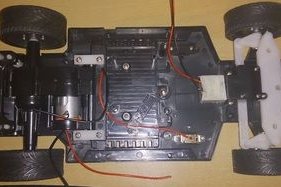
Who have every played with his toy RC car? Today you can turn your old RC car into an advanced Android RC car using Arduino and Bluetooth shield in simple straight forward steps.
First you need to get the car that fits all of those simple components required for the new control circuit. Then you need to get all of the stuff out of it. You can find room for your control board as those modern circuits are much smaller than regular ones.
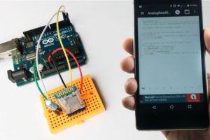
In this post I've found an interesting project to use with Arduino. This is a project where you can upload Arduino Sketches to your Arduino board via Bluetooth connection only.
This means that you only need to connect Arduino board to your PC or Laptop only once for first time programming and configuration and then use your Android Phone to write code, compile and then upload sketches to your Arduino directly via Bluetooth.
Success Story
The maker sure has a very successful story of making and designing. The concept is all built around the powerful Android application that does it all. The maker is so smart as he took the hardware open source approach with his concept. He has even designed his own Arduino Shield that made the same function and compatible with his application. The maker offers the application for free on Google Play Store with the availability to buy the Pro version of the app.
void setup() {
  Serial.begin(38400);
  delay(500);
  Serial.println("AT+NAME=Bluino#00");
  delay(500);
  Serial.println("AT+UART=115200,0,0"); // Use this baudrate if using for Arduino Uno, Bluino and Mega2560
//Serial.println("AT+UART=57600,0,0");  // Use this baudrate if using for Arduino Nano, Leonardo, Micro, Pro Mini 3V3/5V and Duemilanove
  delay(500);
  Serial.println("AT+POLAR=1,0")
  delay(500);
}

void loop() {
}
This step comes first to configure Arduino and Bluetooth module for the process. You need to upload the code to Arduino. This code contains several functions to change the parameters of Bluetooth HC-05 :
AT+NAME=Bluino#00 : Change name of bluetooth module, default name is "HC-05".
AT+BAUD=115200,0,0 : Change baud rate to 115200 (Arduino Uno, Bluino and Mega2560)
AT+BAUD=57600,0,0 : Change baud rate to 57600 (Arduino Nano, Leonardo, Micro, Pro Mini 3V3/5V and Duemilanove)
AT+POLAR=1,0 : Change state pin conditio
For additional you can change password to use not standard password while pairing, AT+PSWD=xxxx.
Note Name of bluetooth must "Bluino#00-9999", if you want custom name you should use the paid version of Bluino Loader App.
Connection
Note the capacitor and resistor connected between Arduino and Bluetooth. Those components are important for resetting Arduino after sketch upload finishes.
Setup Bluetooth HC-05
This is the step where you will run the code you uploaded to Arduino while the Bluetooth module is connected to Arduino.
Note this carefully. You need to force the Bluetooth module into AT command mode using these steps. Press and hold KEY button • Plug USB cable for powering Arduino • Wait about 5 second (still hold KEY button) • Unplug and re plug USB for reset from AT command mode
Install and run the application
The application looks like Arduino IDE
Here you can write, compile and then upload sketches to your Arduino project without having troubles connecting it to PC or Laptop.
Of course the first program that comes in mind when trying this method is the Blink example.
After installing the app you can open example sketch BluinoLoader/examples/02.Basic/Blink/Blink.ino
Tap on "upload" button (Arrow in the circle icon)
After done compiling no error, tap button "Scan Bluino Hardware" to search active bluetooth
Pick bluetooth hardware with name "Bluino#00"
Enter pairing code standard "1234", then OK
Wait until process uploading done
After all steps your Arduino will blink on led 13, and you can repeat all the steps to upload another sketch. Congratulations .. You have made your Bluetooth Programmable Ready Arduino project. Now you can write any code and then compile it and then upload it all using your smart Android. Thanks mansurkamsur. Keep going.
In this post I found this instructable that makes a beautiful yet easy useful toy for your kids. Today I found an Arduino controlled model train that you can move using your phone.
We have seen how it's so easy to control devices using Arduino and Bluetooth module.
This projects implements that idea. It uses Arduino Nano as a controller and HC-06 Bluetooth module to connect to the smartphone. Then the train is driver by the L293D H-Bridge.
In this post we'll learn how to use ArduDroid to control Arduino board in two way communication via Bluetooth using Android smartphone. This Android App uses Bluetooth to connect Arduino to Android phone using serial Bluetooth Module HC-05 or HC-06. Using this App, you can read and write to and from all Arduino board pins and ports. You can read and write to digital ports, you can control PWM ports to write Analog signals, read Analog values from Analog ports and read/write serial data to the Arduino board.
By connecting Arduino board to the Bluetooth module you can gain full control of it. Normally, the code is opensource so the solution can be customized to your needs and configuration. Components Arduino Board Bluetooth Module HC-05 or HC-06 Android Phone ArduDroid App Connection Connect Arduino to the Bluetooth module as the author has chosen or use your own configuration by changing the Arduino code.
Circuit
Code
/*
 PROJECT: ArduDroid
 PROGRAMMER: Hazim Bitar (techbitar at gmail dot com)
 DATE: Oct 31, 2013
 FILE: ardudroid.ino
 LICENSE: Public domain
*/

#define START_CMD_CHAR '*'
#define END_CMD_CHAR '#'
#define DIV_CMD_CHAR '|'
#define CMD_DIGITALWRITE 10
#define CMD_ANALOGWRITE 11
#define CMD_TEXT 12
#define CMD_READ_ARDUDROID 13
#define MAX_COMMAND 20  // max command number code. used for error checking.
#define MIN_COMMAND 10  // minimum command number code. used for error checking.
#define IN_STRING_LENGHT 40
#define MAX_ANALOGWRITE 255
#define PIN_HIGH 3
#define PIN_LOW 2

String inText;

void setup() {
  Serial.begin(9600);
  Serial.println("ArduDroid 0.12 Alpha by TechBitar (2013)");
  Serial.flush();
}

void loop()
{
  Serial.flush();
  int ard_command = 0;
  int pin_num = 0;
  int pin_value = 0;

  char get_char = ' ';  //read serial

  // wait for incoming data
  if (Serial.available() < 1) return; // if serial empty, return to loop().

  // parse incoming command start flag
  get_char = Serial.read();
  if (get_char != START_CMD_CHAR) return; // if no command start flag, return to loop().

  // parse incoming command type
  ard_command = Serial.parseInt(); // read the command

  // parse incoming pin# and value
  pin_num = Serial.parseInt(); // read the pin
  pin_value = Serial.parseInt();  // read the value

  // 1) GET TEXT COMMAND FROM ARDUDROID
  if (ard_command == CMD_TEXT){
    inText =""; //clears variable for new input
    while (Serial.available())  {
      char c = Serial.read();  //gets one byte from serial buffer
      delay(5);
      if (c == END_CMD_CHAR) { // if we the complete string has been read
        // add your code here
        break;
      }
      else {
        if (c !=  DIV_CMD_CHAR) {
          inText += c;
          delay(5);
        }
      }
    }
  }

  // 2) GET digitalWrite DATA FROM ARDUDROID
  if (ard_command == CMD_DIGITALWRITE){
    if (pin_value == PIN_LOW) pin_value = LOW;
    else if (pin_value == PIN_HIGH) pin_value = HIGH;
    else return; // error in pin value. return.
    set_digitalwrite( pin_num,  pin_value);  // Uncomment this function if you wish to use
    return;  // return from start of loop()
  }

  // 3) GET analogWrite DATA FROM ARDUDROID
  if (ard_command == CMD_ANALOGWRITE) {
    analogWrite(  pin_num, pin_value );
    // add your code here
    return;  // Done. return to loop();
  }

  // 4) SEND DATA TO ARDUDROID
  if (ard_command == CMD_READ_ARDUDROID) {
    // char send_to_android[] = "Place your text here." ;
    // Serial.println(send_to_android);   // Example: Sending text
    Serial.print(" Analog 0 = ");
    Serial.println(analogRead(A0));  // Example: Read and send Analog pin value to Arduino
    return;  // Done. return to loop();
  }
}

// 2a) select the requested pin# for DigitalWrite action
void set_digitalwrite(int pin_num, int pin_value)
{
  switch (pin_num) {
  case 13:
    pinMode(13, OUTPUT);
    digitalWrite(13, pin_value);
    // add your code here
    break;
  case 12:
    pinMode(12, OUTPUT);
    digitalWrite(12, pin_value);
    // add your code here
    break;
  case 11:
    pinMode(11, OUTPUT);
    digitalWrite(11, pin_value);
    // add your code here
    break;
  case 10:
    pinMode(10, OUTPUT);
    digitalWrite(10, pin_value);
    // add your code here
    break;
  case 9:
    pinMode(9, OUTPUT);
    digitalWrite(9, pin_value);
    // add your code here
    break;
  case 8:
    pinMode(8, OUTPUT);
    digitalWrite(8, pin_value);
    // add your code here
    break;
  case 7:
    pinMode(7, OUTPUT);
    digitalWrite(7, pin_value);
    // add your code here
    break;
  case 6:
    pinMode(6, OUTPUT);
    digitalWrite(6, pin_value);
    // add your code here
    break;
  case 5:
    pinMode(5, OUTPUT);
    digitalWrite(5, pin_value);
    // add your code here
    break;
  case 4:
    pinMode(4, OUTPUT);
    digitalWrite(4, pin_value);
    // add your code here
    break;
  case 3:
    pinMode(3, OUTPUT);
    digitalWrite(3, pin_value);
    // add your code here
    break;
  case 2:
    pinMode(2, OUTPUT);
    digitalWrite(2, pin_value);
    // add your code here
    break;
    // default:
    // if nothing else matches, do the default
    // default is optional
  }
}
In this post, I'll show you how to make a beautiful Arduino RGB Mood Light that can be controlled via Bluetooth.
The circuit is very simple. You only connect Arduino to the Bluetooth module. Most popular are HC-05 and HC-06 modules. They are inexpensive and easy to use. You can use them to send and receive data to and from Arduino like any serial device.
They have reliable Bluetooth connection with phones and there are many Apps out there that can be used with Arduino projects. Components • 1x Arduino uno • 1x Bluetooth module (HC-05) or HC-06 • 4x RGB LEDs • 1x 9v Battery • 4x 100 ohm resistor • 1x 9v Battery clip • Female-Male jumper wires • Rainbow cable • Perfboard Connections Connect the BT module to Arduino Vcc ---- Arduino 3.3v or 5v (according to your module) Gnd ---- Arduino gnd Rx ---- Arduino Tx
Tx ---- Arduino Rx
LED Connection to Arduino
Code Android Software The post says that there is a link for the Android App that controls the Bluetooth module. But unfortunately, I couldn't find any link to the App. Thus I searched and found many applications on Google play and Amazon that can make the function of controlling the Bluetooth module and Arduino board. You can download any of them and start your own Arduino Application. Here are some of them ArduDroid Arduino Bluetooth Control Ardroid //pins for the LEDs: const int redPin = 3; const int greenPin = 5; const int bluePin = 6; const int redPin2 = 9; const int greenPin2 = 10; const int bluePin2 = 11; #define REDPIN 3 #define GREENPIN 5 #define BLUEPIN 6 #define FADESPEED 5 void setup() { // initialize serial: Serial.begin(9600); // make the pins outputs: pinMode(redPin, OUTPUT); pinMode(greenPin, OUTPUT); pinMode(bluePin, OUTPUT); pinMode(redPin2, OUTPUT); pinMode(greenPin2, OUTPUT); pinMode(bluePin2, OUTPUT); Serial.print("Arduino control RGB LEDs Connected OK ( Sent From Arduinno Board )"); Serial.print('\n'); } void loop() { // if there's any serial available, read it: while (Serial.available() > 0) {
// look for the next valid integer in the incoming serial stream: int red = Serial.parseInt(); // do it again: int green = Serial.parseInt(); // do it again: int blue = Serial.parseInt(); int red2 = Serial.parseInt(); // do it again: int green2 = Serial.parseInt(); // do it again: int blue2 = Serial.parseInt(); // look for the newline. That's the end of your // sentence: if (Serial.read() == '\n') { // constrain the values to 0 - 255 and invert // if you're using a common-cathode LED, just use "constrain(color, 0, 255);" // This is for COMMON ANODE //red = 255 - constrain(red, 0, 255); //green = 255 - constrain(green, 0, 255); //blue = 255 - constrain(blue, 0, 255); red = constrain(red, 0, 255); green = constrain(green, 0, 255); blue = constrain(blue, 0, 255); red2 = constrain(red2, 0, 255); green2 = constrain(green2, 0, 255); blue2 = constrain(blue2, 0, 255); // fade the red, green, and blue legs of the LED: analogWrite(redPin, red); analogWrite(greenPin, green); analogWrite(bluePin, blue); analogWrite(redPin2, red2); analogWrite(greenPin2, green2); analogWrite(bluePin2, blue2); // print the three numbers in one string as hexadecimal: Serial.print("Data Response : "); Serial.print(red, HEX); Serial.print(green, HEX); Serial.println(blue, HEX); } } }


![A Trip To Siwa Oasis: Tourist guide to an Egyptian Oasis by [ElSakhawy, Sara M.]](https://images-na.ssl-images-amazon.com/images/I/51-IGAzLKML.jpg)
![The Ultimate travel bag list by [ Elskhawy, Sara M.]](https://images-na.ssl-images-amazon.com/images/I/51OlVgqIcwL.jpg)
![Why to Travel?: Travel Like an Insider by [M., Sara]](https://images-na.ssl-images-amazon.com/images/I/51BsVhmk3ZL.jpg)
![3 Easy steps to plan your trip: Travel Like an Insider by [Elskhawy, Sara M.]](https://images-na.ssl-images-amazon.com/images/I/51GRc%2BnSxAL.jpg)
![Solar Artwork: How to Make Your Own Solar Masterpiece by [Ebeed, Ahmed]](https://images-na.ssl-images-amazon.com/images/I/51wT6i0RXNL.jpg)
![Backyard Wind Turbines: Harness wind power with simple and fun projects by [Ebeed, Ahmed]](https://images-na.ssl-images-amazon.com/images/I/51JEcdMP8JL.jpg)