How to use #Arduino with #Vibration #Motor on #Tinkercad https://youtu.be/5jdq5688Drc via @YouTube

Embedded systems design, Microchip PIC , Microcontroller , Electronics , Software , Computer , PC,Embedded Systems in Egypt , Microcontroller companies in Egypt , Microcontroller Tutorial for beginners, Microchip Microcontrollers tutorial , Microcontrollers made easy, Microcontroller DIY, DIY,embedded systems,embedded system , open source embedded software,list of embedded systems companies in Egypt, Quadcopter , Embedded Systems components in Egypt , Embedded Systems Components Stores in Egypt
Mturk Jobs

Mturk Jobs
Showing posts with label Arduino UNO. Show all posts
Showing posts with label Arduino UNO. Show all posts
Thursday, March 3, 2022


Monday, August 12, 2019
Simple and Straight Forward: Drive a 220V / 16A Relay With Arduino - How Drive 12V Relay with Arduino
This is a simple circuit for driving 220V/16A Relay with Arduino UNO.

Why use relay with Arduino?
You need to use a relay to control devices and appliances with Arduino. As you already know, Arduino - like all Microcontrollers - has many GPIOs that have 5V output. And you need to drive devices using 220V for operation. Here comes the rule of relay. It's an electromechanical device that can be electrically controlled to control high voltage and currents.

12V - 220V/16A Relay
Diode
10K Ohm Resistor
2N2222 NPN Transistor
Arduino UNO
Wires
Soldering Iron
Soldering Wire
Breadboard
1mm Copper Wire
Drive a Relay With a Transistor - Transistor As a Switch
But if you want to drive a relay with Arduino here comes another challenge. Arduino GPIO output voltage is only 5V and limited current. But the relay in hand needs 12V to energize its relay and it draws larger current than that what Arduino can support.
You then use transistor as a switch.


This is a powerful circuit that makes you drive a relay using Arduino with a transistor as a switch for the larger voltage and current that the relay's coil uses.
In short, you can use a 5V Output PIN from Arduino to drive a large device that is 220V operated by bootstrapping a 12V relay using a 5V operated transistor.

Circuit
If you are like me, then you may want to take a fast look at the schematics of the circuit. So here it is.

Just a simple circuit that contains our transistor, diode, resistor and of course, the relay.
Transistor acts as a switch to control the 12V to relay coil.
Diode acts as a protection for transistor against back EMF induced through relay coil during transit conditions.
Resistor adjusts input current from Arduino to the transistor.
I had an old Microwave over that had its Megatron defected (that's the most expensive part of the Microwave Oven).


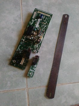


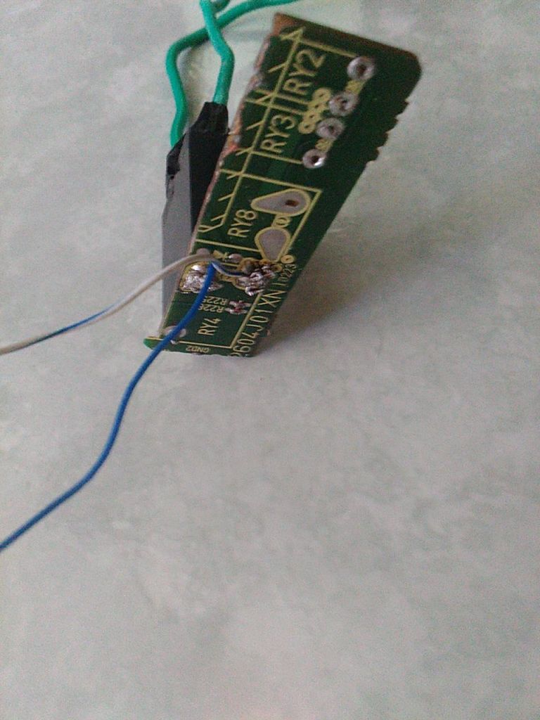


So I used parts from it in many projects. And here I used its control panel.
The relay that drives the Megatron (Microwave Generator) has a 12V control voltage and it can drive a 220V/16A device trough its coil.
I also found a transistor that I took and used for the same purpose.
As for the diode, I found a small surface mount diode soldered under the relay on the Microwave control panel circuit board. You can see it in the photo and you can also note the diode sign on the printed board.
Prepare and Start Assembling
So I used the board as it is.
I used a saw to cut the printed board to get the relay and the diode with their footprints on the printed board.
And it worked great.
So I only needed to solder wires on the relay control pins. And then I connected a 1mm copper wire to the coil contacts. Those are the wires that hold the high voltage/ high current.

Connect to Arduino, Upload Software and Run the Test

Here I connected Arduino UNO Board to the circuit. I connected the 10K Ohm to the PIN 12 of Arduino UNO to get its output.

Note:
Connect relay and transistor VCC and GND to the 12V power supply and not from 5V from Arduino.
I opened Arduino IDE and then opened the famous Blink Example. I added 3 lines of code to add output on PIN 12 besides LED PIN 13. This makes synchronized visual and audible feedback from both LED and Relay.
Compile the sketch and upload it to Arduino.
Run and Have fun.
Read this post on my page on instructables.com
https://www.instructables.com/id/Simple-and-Straight-Forward-Drive-a-220V-16A-Relay/
https://www.instructables.com/id/Simple-and-Straight-Forward-Drive-a-220V-16A-Relay/
Thank you for reading.
Monday, June 25, 2018
Cool and Simple Arduino Metal Detector
We all love Arduino and look for cool ways to make new stuff with it.
This post is dedicated to our Facebook Page fan AbdUllah Hanfy . Thank you for sharing ideas about new ways of using Arduino. If anyone has a new idea about using Arduino in a new or productive circuit don't hesitate to share or ask.
This post is about Metal Detector Circuit. It's about using Arduino as the main controller for the Metal Detector.
I've searched the web and found many circuits of Metal Detectors. Some are as simple as built around the famous 555 timer IC and some are based on Arduino and others are so sophisticated with LCD touch screens.
I believe in simplicity in electronic circuits. Here I'm introducing a fairly simple yet efficient Arduino Metal Detector.
It's simple that it uses limited number of components. And it's efficient as it does its function in detecting metal in fail accuracy and giving visual and audible indications.
I hope you like it. So let's get started.
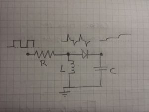 This Metal Detector operates using the self inductance in different metals. As the coil comes near a magnetic metal such as Iron, the coil inductance increases and as the coil comes near a non magnetic material such as Copper, the inductance decreases.
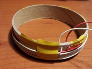
As a rule of thumb, the detector is sensitive to objects at a distance or depth up to the radius of the coil. It is most sensitive to objects in which a current can flow in the plane of the coil, and the response will correspond to the area of the current loop in that object.
The function of the circuit is continuous measurement of the coil impedance and determining the presence of metal of both types.
10nF capacitor
Small signal diode, e.g. 1N4148
220-ohm resistor
For power:
USB power bank with cable
For visual output:
2 LEDs of different colour e.g. blue and green
2 X 220Ohm resistors
For sound output:
Passive buzzer
Microswitch to disable sound
For earphone output:
Earphone connector
1 k Ohm resistor
Earphones
To easily connect/disconnect the search coil:
2 pin screw terminal
For the search coil:
~5 meters of thin electric cable
Structure to hold the coil. Must be stiff but does not need to be circular.
For the structure:
1 meter stick, e.g wood, plastic or selfie stick.
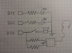
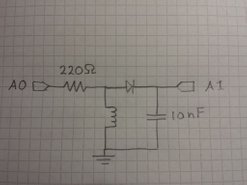
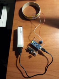
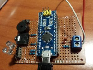
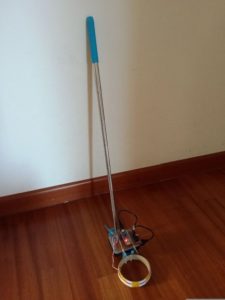
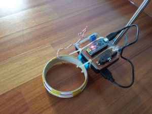
// Metal detector
// Runs a pulse over the search loop in series with resistor
// Voltage over search loop spikes
// Through a diode this charges a capacitor
// Value of capacitor after series of pulses is read by ADC
// Metal objects near search loop change inductance.
// ADC reading depends on inductance.
// changes wrt long-running mean are indicated by LEDs
// LED1 indicates rise in inductance
// LED2 indicates fall in inductance
// the flash rate indicates how large the difference is
// wiring:
// 220Ohm resistor on D2
// 10-loop D=10cm seach loop between ground and resistor
// diode (-) on pin A0 and (+) on loop-resistor connection
// 10nF capacitor between A0 and ground
// LED1 in series with 220Ohm resistor on pin 8
// LED2 in series with 220Ohm resistor on pin 9
// First time, run with with serial print on and tune value of npulse
// to get capacitor reading between 200 and 300
const byte npulse = 3;
const bool sound = true;
const bool debug = false;
const byte pin_pulse=A0;
const byte pin_cap =A1;
const byte pin_LED1 =12;
const byte pin_LED2 =11;
const byte pin_tone =10;
void setup() {
if (debug) Serial.begin(9600);
pinMode(pin_pulse, OUTPUT);
digitalWrite(pin_pulse, LOW);
pinMode(pin_cap, INPUT);
pinMode(pin_LED1, OUTPUT);
digitalWrite(pin_LED1, LOW);
pinMode(pin_LED2, OUTPUT);
digitalWrite(pin_LED2, LOW);
if(sound)pinMode(pin_tone, OUTPUT);
if(sound)digitalWrite(pin_tone, LOW);
}
const int nmeas=256; //measurements to take
long int sumsum=0; //running sum of 64 sums
long int skip=0; //number of skipped sums
long int diff=0; //difference between sum and avgsum
long int flash_period=0;//period (in ms)
long unsigned int prev_flash=0; //time stamp of previous flash
void loop() {
int minval=1023;
int maxval=0;
//perform measurement
long unsigned int sum=0;
for (int imeas=0; imeas//reset the capacitor
pinMode(pin_cap,OUTPUT);
digitalWrite(pin_cap,LOW);
delayMicroseconds(20);
pinMode(pin_cap,INPUT);
//apply pulses
for (int ipulse = 0; ipulse < npulse; ipulse++) {
digitalWrite(pin_pulse,HIGH); //takes 3.5 microseconds
delayMicroseconds(3);
digitalWrite(pin_pulse,LOW); //takes 3.5 microseconds
delayMicroseconds(3);
}
//read the charge on the capacitor
int val = analogRead(pin_cap); //takes 13x8=104 microseconds
minval = min(val,minval);
maxval = max(val,maxval);
sum+=val;
//determine if LEDs should be on or off
long unsigned int timestamp=millis();
byte ledstat=0;
if (timestampif (diff>0)ledstat=1;
if (diff<0 ledstat="2;<br">}
if (timestamp>prev_flash+flash_period){
if (diff>0)ledstat=1;
if (diff<0 ledstat="2;<br">prev_flash=timestamp;
}
if (flash_period>1000)ledstat=0;
//switch the LEDs to this setting
if (ledstat==0){
digitalWrite(pin_LED1,LOW);
digitalWrite(pin_LED2,LOW);
if(sound)noTone(pin_tone);
}
if (ledstat==1){
digitalWrite(pin_LED1,HIGH);
digitalWrite(pin_LED2,LOW);
if(sound)tone(pin_tone,2000);
}
if (ledstat==2){
digitalWrite(pin_LED1,LOW);
digitalWrite(pin_LED2,HIGH);
if(sound)tone(pin_tone,500);
}
}
//subtract minimum and maximum value to remove spikes
sum-=minval; sum-=maxval;
//process
if (sumsum==0) sumsum=sum<<6 br="" expected="" set="" sumsum="" to="" value="">long int avgsum=(sumsum+32)>>6;
diff=sum-avgsum;
if (abs(diff)>10){ //adjust for small changes
sumsum=sumsum+sum-avgsum;
skip=0;
} else {
skip++;
}
if (skip>64){ // break off in case of prolonged skipping
sumsum=sum<<6 br="">skip=0;
}
// one permille change = 2 ticks/s
if (diff==0) flash_period=1000000;
else flash_period=avgsum/(2*abs(diff));
if (debug){
Serial.print(nmeas);
Serial.print(" ");
Serial.print(minval);
Serial.print(" ");
Serial.print(maxval);
Serial.print(" ");
Serial.print(sum);
Serial.print(" ");
Serial.print(avgsum);
Serial.print(" ");
Serial.print(diff);
Serial.print(" ");
Serial.print(flash_period);
Serial.println();
}
}
Source: Instructables
Check our books on Amazon:


This post is dedicated to our Facebook Page fan AbdUllah Hanfy . Thank you for sharing ideas about new ways of using Arduino. If anyone has a new idea about using Arduino in a new or productive circuit don't hesitate to share or ask.
This post is about Metal Detector Circuit. It's about using Arduino as the main controller for the Metal Detector.
I've searched the web and found many circuits of Metal Detectors. Some are as simple as built around the famous 555 timer IC and some are based on Arduino and others are so sophisticated with LCD touch screens.
I believe in simplicity in electronic circuits. Here I'm introducing a fairly simple yet efficient Arduino Metal Detector.
It's simple that it uses limited number of components. And it's efficient as it does its function in detecting metal in fail accuracy and giving visual and audible indications.
I hope you like it. So let's get started.
Theory of operation
As a rule of thumb, the detector is sensitive to objects at a distance or depth up to the radius of the coil. It is most sensitive to objects in which a current can flow in the plane of the coil, and the response will correspond to the area of the current loop in that object.
The function of the circuit is continuous measurement of the coil impedance and determining the presence of metal of both types.
Components
Arduino UNO R310nF capacitor
Small signal diode, e.g. 1N4148
220-ohm resistor
For power:
USB power bank with cable
For visual output:
2 LEDs of different colour e.g. blue and green
2 X 220Ohm resistors
For sound output:
Passive buzzer
Microswitch to disable sound
For earphone output:
Earphone connector
1 k Ohm resistor
Earphones
To easily connect/disconnect the search coil:
2 pin screw terminal
For the search coil:
~5 meters of thin electric cable
Structure to hold the coil. Must be stiff but does not need to be circular.
For the structure:
1 meter stick, e.g wood, plastic or selfie stick.
The Coil
Nearly 20 turns of wire.Connections
Circuit
Final Assembly
Software
// Metal detector
// Runs a pulse over the search loop in series with resistor
// Voltage over search loop spikes
// Through a diode this charges a capacitor
// Value of capacitor after series of pulses is read by ADC
// Metal objects near search loop change inductance.
// ADC reading depends on inductance.
// changes wrt long-running mean are indicated by LEDs
// LED1 indicates rise in inductance
// LED2 indicates fall in inductance
// the flash rate indicates how large the difference is
// wiring:
// 220Ohm resistor on D2
// 10-loop D=10cm seach loop between ground and resistor
// diode (-) on pin A0 and (+) on loop-resistor connection
// 10nF capacitor between A0 and ground
// LED1 in series with 220Ohm resistor on pin 8
// LED2 in series with 220Ohm resistor on pin 9
// First time, run with with serial print on and tune value of npulse
// to get capacitor reading between 200 and 300
const byte npulse = 3;
const bool sound = true;
const bool debug = false;
const byte pin_pulse=A0;
const byte pin_cap =A1;
const byte pin_LED1 =12;
const byte pin_LED2 =11;
const byte pin_tone =10;
void setup() {
if (debug) Serial.begin(9600);
pinMode(pin_pulse, OUTPUT);
digitalWrite(pin_pulse, LOW);
pinMode(pin_cap, INPUT);
pinMode(pin_LED1, OUTPUT);
digitalWrite(pin_LED1, LOW);
pinMode(pin_LED2, OUTPUT);
digitalWrite(pin_LED2, LOW);
if(sound)pinMode(pin_tone, OUTPUT);
if(sound)digitalWrite(pin_tone, LOW);
}
const int nmeas=256; //measurements to take
long int sumsum=0; //running sum of 64 sums
long int skip=0; //number of skipped sums
long int diff=0; //difference between sum and avgsum
long int flash_period=0;//period (in ms)
long unsigned int prev_flash=0; //time stamp of previous flash
void loop() {
int minval=1023;
int maxval=0;
//perform measurement
long unsigned int sum=0;
for (int imeas=0; imeas
pinMode(pin_cap,OUTPUT);
digitalWrite(pin_cap,LOW);
delayMicroseconds(20);
pinMode(pin_cap,INPUT);
//apply pulses
for (int ipulse = 0; ipulse < npulse; ipulse++) {
digitalWrite(pin_pulse,HIGH); //takes 3.5 microseconds
delayMicroseconds(3);
digitalWrite(pin_pulse,LOW); //takes 3.5 microseconds
delayMicroseconds(3);
}
//read the charge on the capacitor
int val = analogRead(pin_cap); //takes 13x8=104 microseconds
minval = min(val,minval);
maxval = max(val,maxval);
sum+=val;
//determine if LEDs should be on or off
long unsigned int timestamp=millis();
byte ledstat=0;
if (timestamp
if (diff<0 ledstat="2;<br">}
if (timestamp>prev_flash+flash_period){
if (diff>0)ledstat=1;
if (diff<0 ledstat="2;<br">prev_flash=timestamp;
}
if (flash_period>1000)ledstat=0;
//switch the LEDs to this setting
if (ledstat==0){
digitalWrite(pin_LED1,LOW);
digitalWrite(pin_LED2,LOW);
if(sound)noTone(pin_tone);
}
if (ledstat==1){
digitalWrite(pin_LED1,HIGH);
digitalWrite(pin_LED2,LOW);
if(sound)tone(pin_tone,2000);
}
if (ledstat==2){
digitalWrite(pin_LED1,LOW);
digitalWrite(pin_LED2,HIGH);
if(sound)tone(pin_tone,500);
}
}
//subtract minimum and maximum value to remove spikes
sum-=minval; sum-=maxval;
//process
if (sumsum==0) sumsum=sum<<6 br="" expected="" set="" sumsum="" to="" value="">long int avgsum=(sumsum+32)>>6;
diff=sum-avgsum;
if (abs(diff)
sumsum=sumsum+sum-avgsum;
skip=0;
} else {
skip++;
}
if (skip>64){ // break off in case of prolonged skipping
sumsum=sum<<6 br="">skip=0;
}
// one permille change = 2 ticks/s
if (diff==0) flash_period=1000000;
else flash_period=avgsum/(2*abs(diff));
if (debug){
Serial.print(nmeas);
Serial.print(" ");
Serial.print(minval);
Serial.print(" ");
Serial.print(maxval);
Serial.print(" ");
Serial.print(sum);
Serial.print(" ");
Serial.print(avgsum);
Serial.print(" ");
Serial.print(diff);
Serial.print(" ");
Serial.print(flash_period);
Serial.println();
}
}
Testing
Source: Instructables
Check our books on Amazon:

Learn By Making: Embedded Systems Tutorial for Students and Beginners

Embedded Systems, Electronics: My Projects Collection From Instructables
Saturday, June 23, 2018
Connecting Arduino UNO with ESP8266 and to ThingSpeak
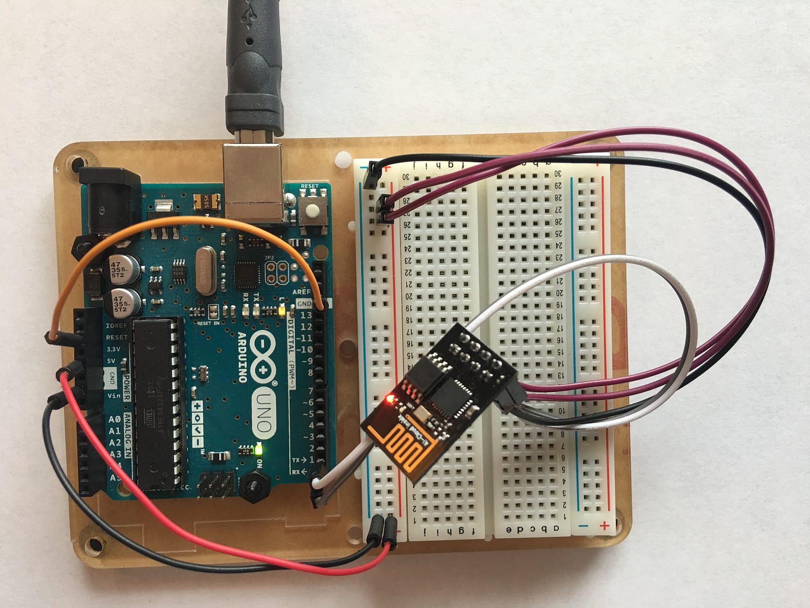
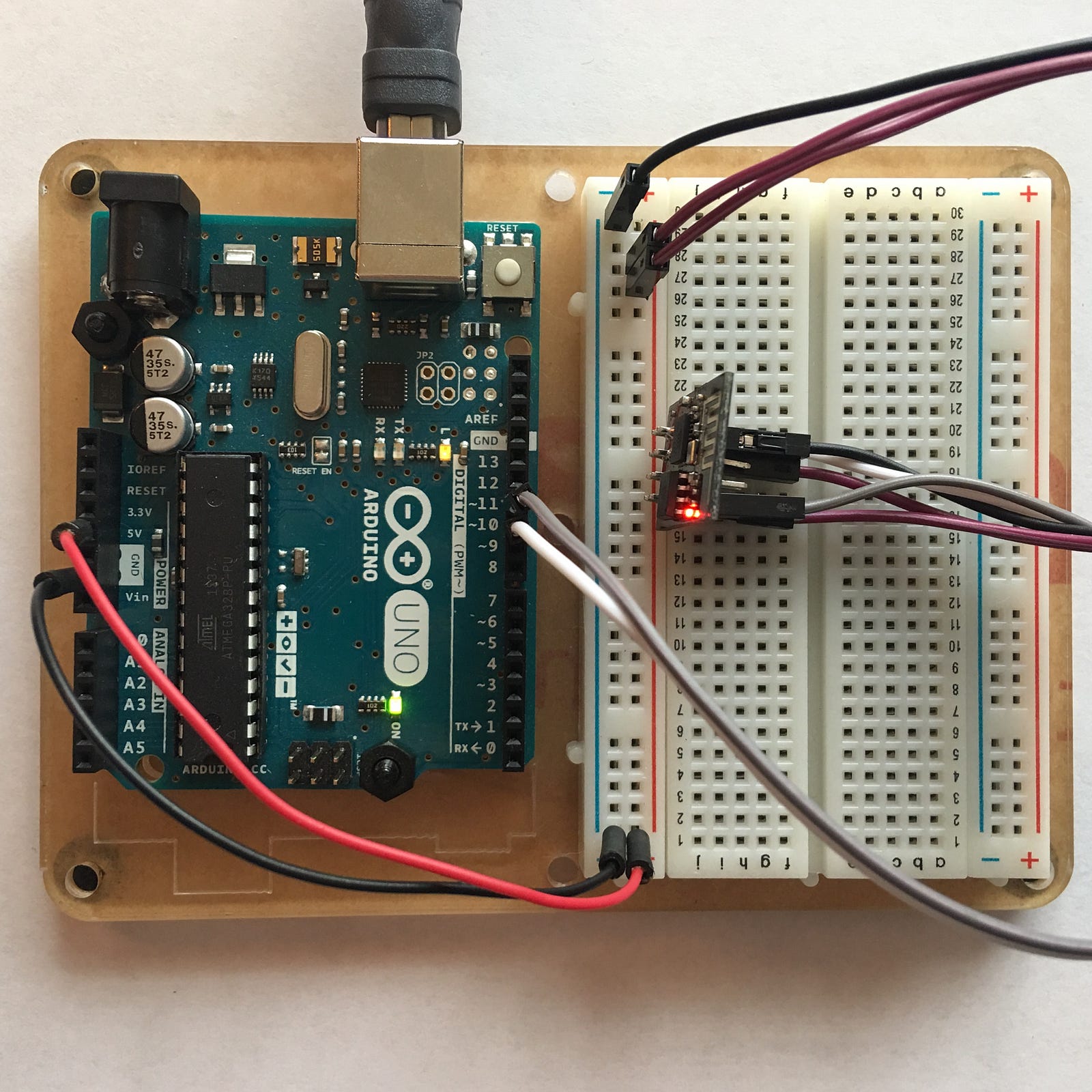
Today I found a great article about how to configure ESP8266 to connect to Arduino UNO in super simple steps and then connect them all to ThingSpeak website.
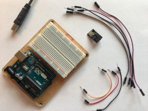
This article is a real treasure to anyone who wants to get started with ESP8266 and doesn't know where to start from.

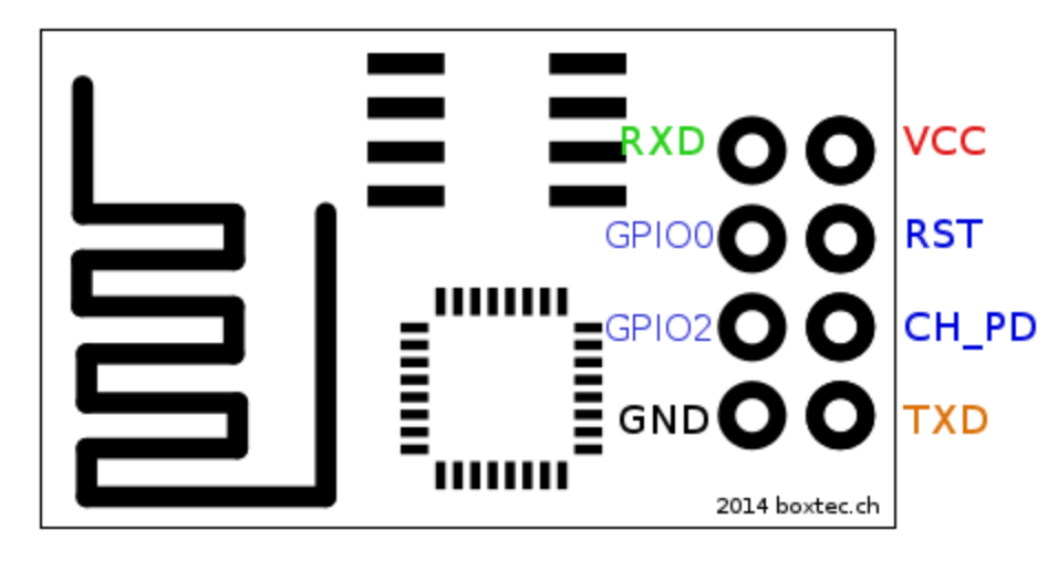 Connection
Code
Source : Medium
Check our books on Amazon:
This article is a real treasure to anyone who wants to get started with ESP8266 and doesn't know where to start from.
What I liked the most about this article and what makes it so special
- The author also clarifies the difference between ESP32 as the newer ESP module and the ESP8266 WIFI Module with basic function.
- Another thing I liked about the article is a new trial the author has made and succeeded in doing it. This trial is by accessing ESP8266 WiFi Module directly but using Arduino UNO as a bridge. I've seen many other programmers and makers who used USB-to-TTL converters and made the task of configuring the module seem so hard. But this author has clarified the steps making it so simple and straightforward.
- Another useful thing I've learned from this article is ThingSpeak. The IoT website that you can use to connect your application and then analyze your data using Matlab tools and all for free.
So let's get started.
Testing the ESP8266 Directly
Esp8266 | Arduino
-----------------
     RX | RX
     TX | TX
    GND | GND
    VCC | 5v
  CH_PD | 5v
 GPIO 0 | None
 GPIO 2 | None
Arduino | Arduino
-----------------
  Reset | GND
Accessing ESP8266 from Arduino Uno code
Esp8266 | Arduino
 — — — — — — — — -
     RX | 11
     TX | 10
    GND | GND (same)
    VCC | 5v (same)
  CH_PD | 5v (same)
 GPIO 0 | None (same)
 GPIO 2 | None (same)
Code
#include
#define RX 10
#define TX 11
String AP = "WIFI_NAME";       // CHANGE ME
String PASS = "WIFI_PASSWORD"; // CHANGE ME
String API = "YOUR_API_KEY";   // CHANGE ME
String HOST = "api.thingspeak.com";
String PORT = "80";
String field = "field1";
int countTrueCommand;
int countTimeCommand;
boolean found = false;
int valSensor = 1;
SoftwareSerial esp8266(RX,TX);


void setup() {
  Serial.begin(9600);
  esp8266.begin(115200);
  sendCommand("AT",5,"OK");
  sendCommand("AT+CWMODE=1",5,"OK");
  sendCommand("AT+CWJAP=\""+ AP +"\",\""+ PASS +"\"",20,"OK");
}
void loop() {
 valSensor = getSensorData();
 String getData = "GET /update?api_key="+ API +"&"+ field +"="+String(valSensor);
sendCommand("AT+CIPMUX=1",5,"OK");
 sendCommand("AT+CIPSTART=0,\"TCP\",\""+ HOST +"\","+ PORT,15,"OK");
 sendCommand("AT+CIPSEND=0," +String(getData.length()+4),4,">");
 esp8266.println(getData);delay(1500);countTrueCommand++;
 sendCommand("AT+CIPCLOSE=0",5,"OK");
}
int getSensorData(){
  return random(1000); // Replace with
}
void sendCommand(String command, int maxTime, char readReplay[]) {
  Serial.print(countTrueCommand);
  Serial.print(". at command => ");
  Serial.print(command);
  Serial.print(" ");
  while(countTimeCommand < (maxTime*1))
  {
    esp8266.println(command);//at+cipsend
    if(esp8266.find(readReplay))//ok
    {
      found = true;
      break;
    }

    countTimeCommand++;
  }

  if(found == true)
  {
    Serial.println("OYI");
    countTrueCommand++;
    countTimeCommand = 0;
  }

  if(found == false)
  {
    Serial.println("Fail");
    countTrueCommand = 0;
    countTimeCommand = 0;
  }

  found = false;
 }
Source : Medium
Check our books on Amazon:
Learn By Making: Embedded Systems Tutorial for Students and Beginners
Embedded Systems, Electronics: My Projects Collection From Instructables
Sunday, May 13, 2018
Arduino IR Heart Rate Monitor - How to measure your heart rate using Arduino and simple electronics
Today I found a simple circuit that uses Arduino and simple electronic components to measure and visualize heart rate.

There are many circuits out there that uses Arduino boards and a special heart rate sensor.
Although I don't yet know the idea behind that heart rate sensor but I think it could be simple.
That's why I searched further until I could find this simple circuit in this post.
This circuit is so simple that it only contains Arduino board and IR transmitter and receiver as the heart rate sensor.
I know this is very simple and primitive, but it's efficient.
You can find many circuits with expensive sensors or larger circuits that use many amplifiers and OP-AMPs.
But this one is fairly simple and enough for the job.
Theory of operation
The IR (infrared) transmitter and receiver are used to measure the blood flow which corresponds to the heart rate.
The Arduino processor then processes the received signal and filters it to get a cleaner indication of the heart rate based on the blood flow in your finger.
Components
Arduino Uno
IR emitter and detector
100 Ohm resistor
10K Ohm resistor
Connections

Circuit

Code
Arduino Code
#include
#include
#include
#include
#include
#include
float amplifiedSignal;
float filteredSignal;
void setup() {
Serial.begin(9600);
}
// filter out frequencies below 1 Hz.
float highFilterFrequency = 1;
// create a highpass filter that only keeps frequencies above highFilterFrequency
FilterOnePole filterOneHighpass( HIGHPASS, highFilterFrequency );
// filters out frequenceies greater than 3 Hz.
float lowFilterFrequency = 3;
// create a lowpass filter that only keeps frequencies below lowFilterFrequency
FilterOnePole filterOneLowpass(LOWPASS, lowFilterFrequency);
void loop() {
//The next line applies a band pass filter to the signal
amplifiedSignal = 100*analogRead(A0);
filteredSignal = filterOneHighpass.input(filterOneLowpass.input(amplifiedSignal));
Serial.println(filteredSignal);
}
Processing code
import processing.serial.*;
Serial myPort; // The serial porthe
int xPos = 1; // horizontal position of the graph
//int xPos = millis()/1000;
//Variables to draw a continuous line.
int lastxPos=1;
int lastheight=0;
int screenWidth = 600;
int screenHeight = 400;
int pulseNumber = 0;
boolean pulseHigh = false;
int startTime;
int stopTime;
int heartRate;
void makeGrid(int screenWidth, int screenHeight){
stroke(0,255,0);
strokeWeight(0.5);
line(0, screenHeight/2, screenWidth, screenHeight/2);
for (int i = 0; i <= 10; i = i+1) {
line(i*screenWidth/10, 0, i*screenWidth/10, screenHeight);
line(0, i*screenHeight/10, screenWidth, i*screenHeight/10);
}
}
void setup () {
// set the window size:
size(screenWidth, screenHeight);
// List all the available serial ports
println(Serial.list());
// Check the listed serial ports in your machine
// and use the correct index number in Serial.list()[].
myPort = new Serial(this, Serial.list()[0], 9600); //
// A serialEvent() is generated when a newline character is received :
myPort.bufferUntil('\n');
background(0); // set inital background:
makeGrid(screenWidth, screenHeight);
}
void draw () {
// everything happens in the serialEvent()
}
void serialEvent (Serial myPort) {
// get the ASCII string:
String inString = myPort.readStringUntil('\n');
if (inString != null) {
inString = trim(inString); // trim off whitespaces.
float inByte = float(inString); // convert to a number.
if (inByte >= 0 && pulseHigh == false){
if (pulseNumber == 0){
startTime = millis();
//println("first");
}
else{
stopTime = millis();
}
pulseNumber = pulseNumber + 1;
//println("next");
pulseHigh = true;
}
else if (inByte <= 0 && pulseHigh == true){
pulseHigh = false;
}
inByte = map(inByte, -1023, 1023, 0, height); //map to the screen height.
//Drawing a line from Last inByte to the new one.
stroke(255,0,0); //stroke color
strokeWeight(4); //stroke wider
line(lastxPos, lastheight, xPos, height - inByte);
lastxPos= xPos;
lastheight= int(height-inByte);
// at the edge of the window, go back to the beginning:
if (xPos >= width) {
xPos = 0;
lastxPos= 0;
background(0); //Clear the screen.
makeGrid(screenWidth, screenHeight);
heartRate = 60*1000*(pulseNumber-1)/(stopTime-startTime);
textSize(16);
//text("This is your heart beat. Your heart rate is " + str(heartRate) + " bpm.", 10, 30);
//fill(0, 102, 153);
pulseNumber = 0;
}
else {
// increment the horizontal position:
xPos++;
}
}
}
Results
Source: Instructables
Check our books on Amazon:

Although I don't yet know the idea behind that heart rate sensor but I think it could be simple.
That's why I searched further until I could find this simple circuit in this post.
This circuit is so simple that it only contains Arduino board and IR transmitter and receiver as the heart rate sensor.
I know this is very simple and primitive, but it's efficient.
You can find many circuits with expensive sensors or larger circuits that use many amplifiers and OP-AMPs.
But this one is fairly simple and enough for the job.
Theory of operation
The IR (infrared) transmitter and receiver are used to measure the blood flow which corresponds to the heart rate.
The Arduino processor then processes the received signal and filters it to get a cleaner indication of the heart rate based on the blood flow in your finger.
Components
Arduino Uno
IR emitter and detector
100 Ohm resistor
10K Ohm resistor
Connections

Circuit

Arduino Code
#include
#include
#include
#include
#include
#include
float amplifiedSignal;
float filteredSignal;
void setup() {
Serial.begin(9600);
}
// filter out frequencies below 1 Hz.
float highFilterFrequency = 1;
// create a highpass filter that only keeps frequencies above highFilterFrequency
FilterOnePole filterOneHighpass( HIGHPASS, highFilterFrequency );
// filters out frequenceies greater than 3 Hz.
float lowFilterFrequency = 3;
// create a lowpass filter that only keeps frequencies below lowFilterFrequency
FilterOnePole filterOneLowpass(LOWPASS, lowFilterFrequency);
void loop() {
//The next line applies a band pass filter to the signal
amplifiedSignal = 100*analogRead(A0);
filteredSignal = filterOneHighpass.input(filterOneLowpass.input(amplifiedSignal));
Serial.println(filteredSignal);
}
Processing code
import processing.serial.*;
Serial myPort; // The serial porthe
int xPos = 1; // horizontal position of the graph
//int xPos = millis()/1000;
//Variables to draw a continuous line.
int lastxPos=1;
int lastheight=0;
int screenWidth = 600;
int screenHeight = 400;
int pulseNumber = 0;
boolean pulseHigh = false;
int startTime;
int stopTime;
int heartRate;
void makeGrid(int screenWidth, int screenHeight){
stroke(0,255,0);
strokeWeight(0.5);
line(0, screenHeight/2, screenWidth, screenHeight/2);
for (int i = 0; i <= 10; i = i+1) {
line(i*screenWidth/10, 0, i*screenWidth/10, screenHeight);
line(0, i*screenHeight/10, screenWidth, i*screenHeight/10);
}
}
void setup () {
// set the window size:
size(screenWidth, screenHeight);
// List all the available serial ports
println(Serial.list());
// Check the listed serial ports in your machine
// and use the correct index number in Serial.list()[].
myPort = new Serial(this, Serial.list()[0], 9600); //
// A serialEvent() is generated when a newline character is received :
myPort.bufferUntil('\n');
background(0); // set inital background:
makeGrid(screenWidth, screenHeight);
}
void draw () {
// everything happens in the serialEvent()
}
void serialEvent (Serial myPort) {
// get the ASCII string:
String inString = myPort.readStringUntil('\n');
if (inString != null) {
inString = trim(inString); // trim off whitespaces.
float inByte = float(inString); // convert to a number.
if (inByte >= 0 && pulseHigh == false){
if (pulseNumber == 0){
startTime = millis();
//println("first");
}
else{
stopTime = millis();
}
pulseNumber = pulseNumber + 1;
//println("next");
pulseHigh = true;
}
else if (inByte <= 0 && pulseHigh == true){
pulseHigh = false;
}
inByte = map(inByte, -1023, 1023, 0, height); //map to the screen height.
//Drawing a line from Last inByte to the new one.
stroke(255,0,0); //stroke color
strokeWeight(4); //stroke wider
line(lastxPos, lastheight, xPos, height - inByte);
lastxPos= xPos;
lastheight= int(height-inByte);
// at the edge of the window, go back to the beginning:
if (xPos >= width) {
xPos = 0;
lastxPos= 0;
background(0); //Clear the screen.
makeGrid(screenWidth, screenHeight);
heartRate = 60*1000*(pulseNumber-1)/(stopTime-startTime);
textSize(16);
//text("This is your heart beat. Your heart rate is " + str(heartRate) + " bpm.", 10, 30);
//fill(0, 102, 153);
pulseNumber = 0;
}
else {
// increment the horizontal position:
xPos++;
}
}
}
Results
Source: Instructables

![A Trip To Siwa Oasis: Tourist guide to an Egyptian Oasis by [ElSakhawy, Sara M.]](https://images-na.ssl-images-amazon.com/images/I/51-IGAzLKML.jpg)
![The Ultimate travel bag list by [ Elskhawy, Sara M.]](https://images-na.ssl-images-amazon.com/images/I/51OlVgqIcwL.jpg)
![Why to Travel?: Travel Like an Insider by [M., Sara]](https://images-na.ssl-images-amazon.com/images/I/51BsVhmk3ZL.jpg)
![3 Easy steps to plan your trip: Travel Like an Insider by [Elskhawy, Sara M.]](https://images-na.ssl-images-amazon.com/images/I/51GRc%2BnSxAL.jpg)
![Solar Artwork: How to Make Your Own Solar Masterpiece by [Ebeed, Ahmed]](https://images-na.ssl-images-amazon.com/images/I/51wT6i0RXNL.jpg)
![Backyard Wind Turbines: Harness wind power with simple and fun projects by [Ebeed, Ahmed]](https://images-na.ssl-images-amazon.com/images/I/51JEcdMP8JL.jpg)

Learn By Making: Embedded Systems Tutorial for Students and Beginners
Embedded Systems, Electronics: My Projects Collection From Instructables
Subscribe to:
Posts (Atom)