Embedded systems design, Microchip PIC , Microcontroller , Electronics , Software , Computer , PC,Embedded Systems in Egypt , Microcontroller companies in Egypt , Microcontroller Tutorial for beginners, Microchip Microcontrollers tutorial , Microcontrollers made easy, Microcontroller DIY, DIY,embedded systems,embedded system , open source embedded software,list of embedded systems companies in Egypt, Quadcopter , Embedded Systems components in Egypt , Embedded Systems Components Stores in Egypt
Mturk Jobs
Mturk Jobs
Tank
Showing posts with label Arduino HC-06 Module. Show all posts
Showing posts with label Arduino HC-06 Module. Show all posts
This is a Smartphone Bluetooth controlled RGB Mood light lamp using Arduino and HC-06 Bluetooth Module.
This project is both easy and rewarding. Mood light is a nice project to make for your kids and family. It adds a touch of beauty to your home and warmth to your surroundings. Some of Mood Light projects can be somehow hard to implement. But in this project, I managed to make it as simple as possible. You should be able to complete this project in less than fifteen minutes. The power behind this kind of simplicity comes from the wonderful application and website Remote XY.
You can use it to create any wireless and remote Arduino project from anywhere in the world. Whether you connect your phone to your project using Bluetooth, WIFI or even through the internet, you can always connect them both easily. Also, the design process is much easier than many other platforms. Components
I connected the negative (shorter) leg of the three LEDs together for easy use.
Jumper wires
Connection You need to connect Arduino to the HC-06 Module only through four wires. Arduino HC-06 Vcc Vcc GND GND Tx Rx Rx Tx
Application design Go to RemoteXY.com and open the Editor. Choose connection, device and wireless module. Then you can place application visual controls and indications.
Software Generation
You need to download the generated code from the editor. You also need to include the Remote XY library from the same page.
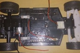
Who have every played with his toy RC car? Today you can turn your old RC car into an advanced Android RC car using Arduino and Bluetooth shield in simple straight forward steps.
First you need to get the car that fits all of those simple components required for the new control circuit. Then you need to get all of the stuff out of it. You can find room for your control board as those modern circuits are much smaller than regular ones.
In this post I found this instructable that makes a beautiful yet easy useful toy for your kids. Today I found an Arduino controlled model train that you can move using your phone.
We have seen how it's so easy to control devices using Arduino and Bluetooth module.
This projects implements that idea. It uses Arduino Nano as a controller and HC-06 Bluetooth module to connect to the smartphone. Then the train is driver by the L293D H-Bridge.
In this post we'll learn how to use ArduDroid to control Arduino board in two way communication via Bluetooth using Android smartphone. This Android App uses Bluetooth to connect Arduino to Android phone using serial Bluetooth Module HC-05 or HC-06. Using this App, you can read and write to and from all Arduino board pins and ports. You can read and write to digital ports, you can control PWM ports to write Analog signals, read Analog values from Analog ports and read/write serial data to the Arduino board.
By connecting Arduino board to the Bluetooth module you can gain full control of it. Normally, the code is opensource so the solution can be customized to your needs and configuration. Components Arduino Board Bluetooth Module HC-05 or HC-06 Android Phone ArduDroid App Connection Connect Arduino to the Bluetooth module as the author has chosen or use your own configuration by changing the Arduino code.
Circuit
Code
/*
 PROJECT: ArduDroid
 PROGRAMMER: Hazim Bitar (techbitar at gmail dot com)
 DATE: Oct 31, 2013
 FILE: ardudroid.ino
 LICENSE: Public domain
*/

#define START_CMD_CHAR '*'
#define END_CMD_CHAR '#'
#define DIV_CMD_CHAR '|'
#define CMD_DIGITALWRITE 10
#define CMD_ANALOGWRITE 11
#define CMD_TEXT 12
#define CMD_READ_ARDUDROID 13
#define MAX_COMMAND 20  // max command number code. used for error checking.
#define MIN_COMMAND 10  // minimum command number code. used for error checking.
#define IN_STRING_LENGHT 40
#define MAX_ANALOGWRITE 255
#define PIN_HIGH 3
#define PIN_LOW 2

String inText;

void setup() {
  Serial.begin(9600);
  Serial.println("ArduDroid 0.12 Alpha by TechBitar (2013)");
  Serial.flush();
}

void loop()
{
  Serial.flush();
  int ard_command = 0;
  int pin_num = 0;
  int pin_value = 0;

  char get_char = ' ';  //read serial

  // wait for incoming data
  if (Serial.available() < 1) return; // if serial empty, return to loop().

  // parse incoming command start flag
  get_char = Serial.read();
  if (get_char != START_CMD_CHAR) return; // if no command start flag, return to loop().

  // parse incoming command type
  ard_command = Serial.parseInt(); // read the command

  // parse incoming pin# and value
  pin_num = Serial.parseInt(); // read the pin
  pin_value = Serial.parseInt();  // read the value

  // 1) GET TEXT COMMAND FROM ARDUDROID
  if (ard_command == CMD_TEXT){
    inText =""; //clears variable for new input
    while (Serial.available())  {
      char c = Serial.read();  //gets one byte from serial buffer
      delay(5);
      if (c == END_CMD_CHAR) { // if we the complete string has been read
        // add your code here
        break;
      }
      else {
        if (c !=  DIV_CMD_CHAR) {
          inText += c;
          delay(5);
        }
      }
    }
  }

  // 2) GET digitalWrite DATA FROM ARDUDROID
  if (ard_command == CMD_DIGITALWRITE){
    if (pin_value == PIN_LOW) pin_value = LOW;
    else if (pin_value == PIN_HIGH) pin_value = HIGH;
    else return; // error in pin value. return.
    set_digitalwrite( pin_num,  pin_value);  // Uncomment this function if you wish to use
    return;  // return from start of loop()
  }

  // 3) GET analogWrite DATA FROM ARDUDROID
  if (ard_command == CMD_ANALOGWRITE) {
    analogWrite(  pin_num, pin_value );
    // add your code here
    return;  // Done. return to loop();
  }

  // 4) SEND DATA TO ARDUDROID
  if (ard_command == CMD_READ_ARDUDROID) {
    // char send_to_android[] = "Place your text here." ;
    // Serial.println(send_to_android);   // Example: Sending text
    Serial.print(" Analog 0 = ");
    Serial.println(analogRead(A0));  // Example: Read and send Analog pin value to Arduino
    return;  // Done. return to loop();
  }
}

// 2a) select the requested pin# for DigitalWrite action
void set_digitalwrite(int pin_num, int pin_value)
{
  switch (pin_num) {
  case 13:
    pinMode(13, OUTPUT);
    digitalWrite(13, pin_value);
    // add your code here
    break;
  case 12:
    pinMode(12, OUTPUT);
    digitalWrite(12, pin_value);
    // add your code here
    break;
  case 11:
    pinMode(11, OUTPUT);
    digitalWrite(11, pin_value);
    // add your code here
    break;
  case 10:
    pinMode(10, OUTPUT);
    digitalWrite(10, pin_value);
    // add your code here
    break;
  case 9:
    pinMode(9, OUTPUT);
    digitalWrite(9, pin_value);
    // add your code here
    break;
  case 8:
    pinMode(8, OUTPUT);
    digitalWrite(8, pin_value);
    // add your code here
    break;
  case 7:
    pinMode(7, OUTPUT);
    digitalWrite(7, pin_value);
    // add your code here
    break;
  case 6:
    pinMode(6, OUTPUT);
    digitalWrite(6, pin_value);
    // add your code here
    break;
  case 5:
    pinMode(5, OUTPUT);
    digitalWrite(5, pin_value);
    // add your code here
    break;
  case 4:
    pinMode(4, OUTPUT);
    digitalWrite(4, pin_value);
    // add your code here
    break;
  case 3:
    pinMode(3, OUTPUT);
    digitalWrite(3, pin_value);
    // add your code here
    break;
  case 2:
    pinMode(2, OUTPUT);
    digitalWrite(2, pin_value);
    // add your code here
    break;
    // default:
    // if nothing else matches, do the default
    // default is optional
  }
}


![A Trip To Siwa Oasis: Tourist guide to an Egyptian Oasis by [ElSakhawy, Sara M.]](https://images-na.ssl-images-amazon.com/images/I/51-IGAzLKML.jpg)
![The Ultimate travel bag list by [ Elskhawy, Sara M.]](https://images-na.ssl-images-amazon.com/images/I/51OlVgqIcwL.jpg)
![Why to Travel?: Travel Like an Insider by [M., Sara]](https://images-na.ssl-images-amazon.com/images/I/51BsVhmk3ZL.jpg)
![3 Easy steps to plan your trip: Travel Like an Insider by [Elskhawy, Sara M.]](https://images-na.ssl-images-amazon.com/images/I/51GRc%2BnSxAL.jpg)
![Solar Artwork: How to Make Your Own Solar Masterpiece by [Ebeed, Ahmed]](https://images-na.ssl-images-amazon.com/images/I/51wT6i0RXNL.jpg)
![Backyard Wind Turbines: Harness wind power with simple and fun projects by [Ebeed, Ahmed]](https://images-na.ssl-images-amazon.com/images/I/51JEcdMP8JL.jpg)