This post is dedicated to our Facebook Page fan AbdUllah Hanfy . Thank you for sharing ideas about new ways of using Arduino. If anyone has a new idea about using Arduino in a new or productive circuit don't hesitate to share or ask.
This post is about Metal Detector Circuit. It's about using Arduino as the main controller for the Metal Detector.
I've searched the web and found many circuits of Metal Detectors. Some are as simple as built around the famous 555 timer IC and some are based on Arduino and others are so sophisticated with LCD touch screens.
I believe in simplicity in electronic circuits. Here I'm introducing a fairly simple yet efficient Arduino Metal Detector.
It's simple that it uses limited number of components. And it's efficient as it does its function in detecting metal in fail accuracy and giving visual and audible indications.
I hope you like it. So let's get started.
Theory of operation
As a rule of thumb, the detector is sensitive to objects at a distance or depth up to the radius of the coil. It is most sensitive to objects in which a current can flow in the plane of the coil, and the response will correspond to the area of the current loop in that object.
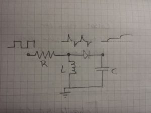
The function of the circuit is continuous measurement of the coil impedance and determining the presence of metal of both types.
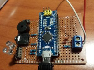
Components
Arduino UNO R310nF capacitor
Small signal diode, e.g. 1N4148
220-ohm resistor
For power:
USB power bank with cable
For visual output:
2 LEDs of different colour e.g. blue and green
2 X 220Ohm resistors
For sound output:
Passive buzzer
Microswitch to disable sound
For earphone output:
Earphone connector
1 k Ohm resistor
Earphones
To easily connect/disconnect the search coil:
2 pin screw terminal
For the search coil:
~5 meters of thin electric cable
Structure to hold the coil. Must be stiff but does not need to be circular.
For the structure:
1 meter stick, e.g wood, plastic or selfie stick.
The Coil
Nearly 20 turns of wire.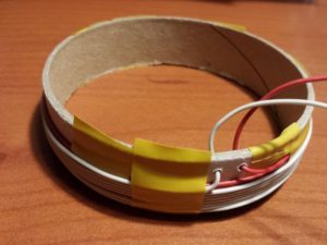
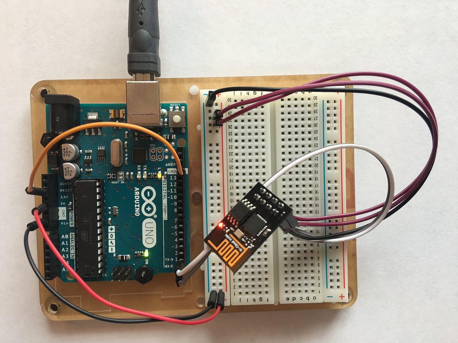
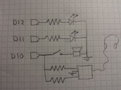
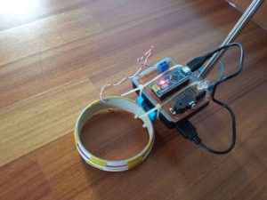
Connections
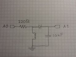
Circuit
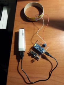
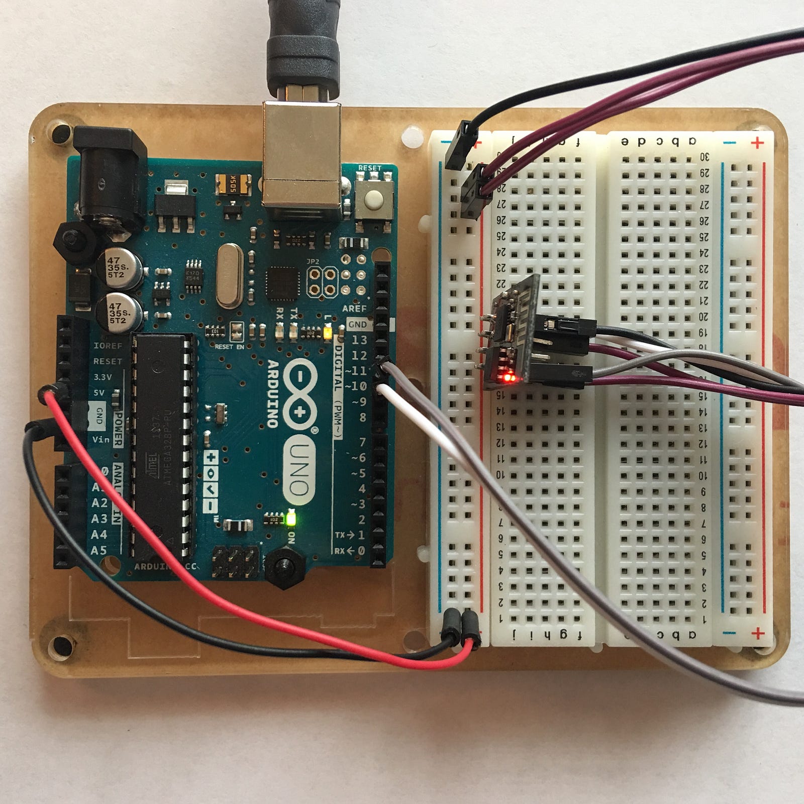
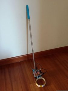
Final Assembly
Software
// Metal detector
// Runs a pulse over the search loop in series with resistor
// Voltage over search loop spikes
// Through a diode this charges a capacitor
// Value of capacitor after series of pulses is read by ADC
// Metal objects near search loop change inductance.
// ADC reading depends on inductance.
// changes wrt long-running mean are indicated by LEDs
// LED1 indicates rise in inductance
// LED2 indicates fall in inductance
// the flash rate indicates how large the difference is
// wiring:
// 220Ohm resistor on D2
// 10-loop D=10cm seach loop between ground and resistor
// diode (-) on pin A0 and (+) on loop-resistor connection
// 10nF capacitor between A0 and ground
// LED1 in series with 220Ohm resistor on pin 8
// LED2 in series with 220Ohm resistor on pin 9
// First time, run with with serial print on and tune value of npulse
// to get capacitor reading between 200 and 300
const byte npulse = 3;
const bool sound = true;
const bool debug = false;
const byte pin_pulse=A0;
const byte pin_cap =A1;
const byte pin_LED1 =12;
const byte pin_LED2 =11;
const byte pin_tone =10;
void setup() {
if (debug) Serial.begin(9600);
pinMode(pin_pulse, OUTPUT);
digitalWrite(pin_pulse, LOW);
pinMode(pin_cap, INPUT);
pinMode(pin_LED1, OUTPUT);
digitalWrite(pin_LED1, LOW);
pinMode(pin_LED2, OUTPUT);
digitalWrite(pin_LED2, LOW);
if(sound)pinMode(pin_tone, OUTPUT);
if(sound)digitalWrite(pin_tone, LOW);
}
const int nmeas=256; //measurements to take
long int sumsum=0; //running sum of 64 sums
long int skip=0; //number of skipped sums
long int diff=0; //difference between sum and avgsum
long int flash_period=0;//period (in ms)
long unsigned int prev_flash=0; //time stamp of previous flash
void loop() {
int minval=1023;
int maxval=0;
//perform measurement
long unsigned int sum=0;
for (int imeas=0; imeas
pinMode(pin_cap,OUTPUT);
digitalWrite(pin_cap,LOW);
delayMicroseconds(20);
pinMode(pin_cap,INPUT);
//apply pulses
for (int ipulse = 0; ipulse < npulse; ipulse++) {
digitalWrite(pin_pulse,HIGH); //takes 3.5 microseconds
delayMicroseconds(3);
digitalWrite(pin_pulse,LOW); //takes 3.5 microseconds
delayMicroseconds(3);
}
//read the charge on the capacitor
int val = analogRead(pin_cap); //takes 13x8=104 microseconds
minval = min(val,minval);
maxval = max(val,maxval);
sum+=val;
//determine if LEDs should be on or off
long unsigned int timestamp=millis();
byte ledstat=0;
if (timestamp
if (diff<0 ledstat="2;<br">}
if (timestamp>prev_flash+flash_period){
if (diff>0)ledstat=1;
if (diff<0 ledstat="2;<br">prev_flash=timestamp;
}
if (flash_period>1000)ledstat=0;
//switch the LEDs to this setting
if (ledstat==0){
digitalWrite(pin_LED1,LOW);
digitalWrite(pin_LED2,LOW);
if(sound)noTone(pin_tone);
}
if (ledstat==1){
digitalWrite(pin_LED1,HIGH);
digitalWrite(pin_LED2,LOW);
if(sound)tone(pin_tone,2000);
}
if (ledstat==2){
digitalWrite(pin_LED1,LOW);
digitalWrite(pin_LED2,HIGH);
if(sound)tone(pin_tone,500);
}
}
//subtract minimum and maximum value to remove spikes
sum-=minval; sum-=maxval;
//process
if (sumsum==0) sumsum=sum<<6 br="" expected="" set="" sumsum="" to="" value="">long int avgsum=(sumsum+32)>>6;
diff=sum-avgsum;
if (abs(diff)
sumsum=sumsum+sum-avgsum;
skip=0;
} else {
skip++;
}
if (skip>64){ // break off in case of prolonged skipping
sumsum=sum<<6 br="">skip=0;
}
// one permille change = 2 ticks/s
if (diff==0) flash_period=1000000;
else flash_period=avgsum/(2*abs(diff));
if (debug){
Serial.print(nmeas);
Serial.print(" ");
Serial.print(minval);
Serial.print(" ");
Serial.print(maxval);
Serial.print(" ");
Serial.print(sum);
Serial.print(" ");
Serial.print(avgsum);
Serial.print(" ");
Serial.print(diff);
Serial.print(" ");
Serial.print(flash_period);
Serial.println();
}
}
Testing
Source: Instructables
Check our books on Amazon:

Learn By Making: Embedded Systems Tutorial for Students and Beginners