

This is a simple circuit for driving 220V/16A Relay with Arduino UNO.

Why use relay with Arduino?
You need to use a relay to control devices and appliances with Arduino. As you already know, Arduino - like all Microcontrollers - has many GPIOs that have 5V output. And you need to drive devices using 220V for operation. Here comes the rule of relay. It's an electromechanical device that can be electrically controlled to control high voltage and currents.

12V - 220V/16A Relay
Diode
10K Ohm Resistor
2N2222 NPN Transistor
Arduino UNO
Wires
Soldering Iron
Soldering Wire
Breadboard
1mm Copper Wire
Drive a Relay With a Transistor - Transistor As a Switch
But if you want to drive a relay with Arduino here comes another challenge. Arduino GPIO output voltage is only 5V and limited current. But the relay in hand needs 12V to energize its relay and it draws larger current than that what Arduino can support.
You then use transistor as a switch.


This is a powerful circuit that makes you drive a relay using Arduino with a transistor as a switch for the larger voltage and current that the relay's coil uses.
In short, you can use a 5V Output PIN from Arduino to drive a large device that is 220V operated by bootstrapping a 12V relay using a 5V operated transistor.

Circuit
If you are like me, then you may want to take a fast look at the schematics of the circuit. So here it is.

Just a simple circuit that contains our transistor, diode, resistor and of course, the relay.
Transistor acts as a switch to control the 12V to relay coil.
Diode acts as a protection for transistor against back EMF induced through relay coil during transit conditions.
Resistor adjusts input current from Arduino to the transistor.
I had an old Microwave over that had its Megatron defected (that's the most expensive part of the Microwave Oven).


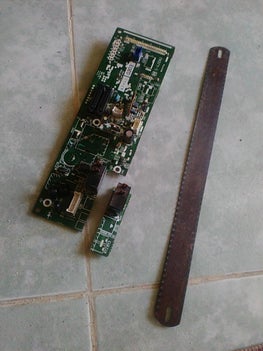


So I used parts from it in many projects. And here I used its control panel.
The relay that drives the Megatron (Microwave Generator) has a 12V control voltage and it can drive a 220V/16A device trough its coil.
I also found a transistor that I took and used for the same purpose.
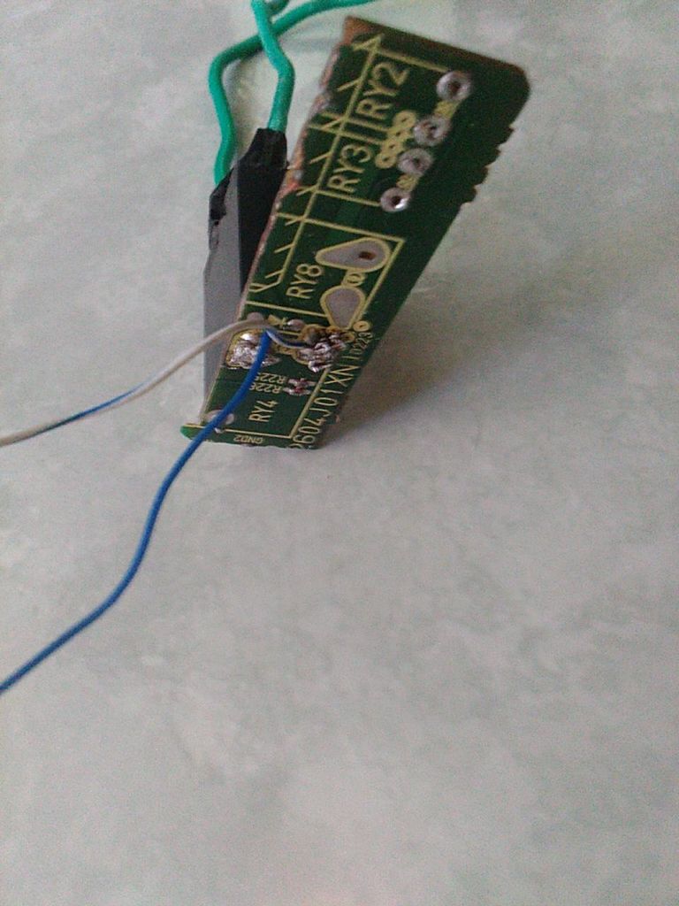
As for the diode, I found a small surface mount diode soldered under the relay on the Microwave control panel circuit board. You can see it in the photo and you can also note the diode sign on the printed board.
Prepare and Start Assembling
So I used the board as it is.
I used a saw to cut the printed board to get the relay and the diode with their footprints on the printed board.
And it worked great.
So I only needed to solder wires on the relay control pins. And then I connected a 1mm copper wire to the coil contacts. Those are the wires that hold the high voltage/ high current.

Connect to Arduino, Upload Software and Run the Test

Here I connected Arduino UNO Board to the circuit. I connected the 10K Ohm to the PIN 12 of Arduino UNO to get its output.

Note:
Connect relay and transistor VCC and GND to the 12V power supply and not from 5V from Arduino.
I opened Arduino IDE and then opened the famous Blink Example. I added 3 lines of code to add output on PIN 12 besides LED PIN 13. This makes synchronized visual and audible feedback from both LED and Relay.
Compile the sketch and upload it to Arduino.
Run and Have fun.
Read this post on my page on instructables.com
https://www.instructables.com/id/Simple-and-Straight-Forward-Drive-a-220V-16A-Relay/
https://www.instructables.com/id/Simple-and-Straight-Forward-Drive-a-220V-16A-Relay/
Thank you for reading.