Do you know Segway?
Segway is a Self Balancing two wheeled Scooter.
It uses motion and acceleration sensor to detect its orientation and then achieve self balance.
Today we are going to see how this self balancing robot is made.
Arduino Mini or Uno
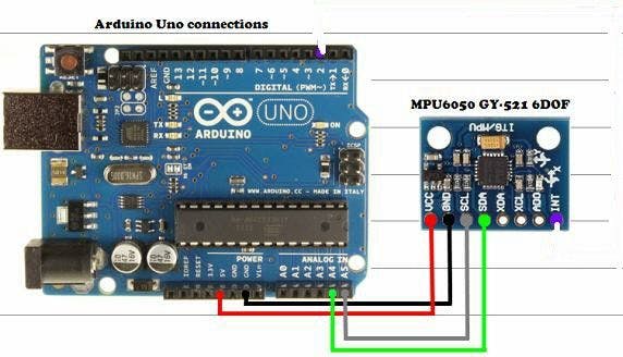
MPU6050
L293D IC
2 DC Motors
2 Wheels
Some wires
Mechanical Design
Battery
The concept of operation is very simple.
When the scooter senses that it is tilted forward, it moves faster to the forward.
And when it senses that it is tilting behind, it moves faster to backwards.
In this way, it tries to balance itself so fast all the time using motion sensor information and processing power of Arduino.
Connection
Here is how to connect motion sensor to Arduino
And this is the L293D IC to Arduino
Here is the complete project connection
Code
#include
#include "Kalman.h" // Source: https://github.com/TKJElectronics/KalmanFilter
#define RESTRICT_PITCH
Kalman kalmanX;
Kalman kalmanY;
double accX, accY, accZ;
double gyroX, gyroY, gyroZ;
int16_t tempRaw;

double gyroXangle, gyroYangle; // Gyroscope angle
double compAngleX, compAngleY; // Complementary filter angle
double kalAngleX, kalAngleY; // Angle after Kalman filter
double corrected_x, corrected_y; // Corrected with offset

uint32_t timer;
uint8_t i2cData[14]; // Buffer for I2C data

char a;
double m = 0.7;
double m1 = -0.7;
int d = 0;
int c = 0;
char p;
int in1_motor_left = 8;
int in2_motor_left = 7;
int in3_motor_right = 3;
int in4_motor_right = 4;
int pwm_on = 5; // ms ON
int pwm_off = 5; // ms OFF
//------------------------------------------------------------------------------
void setup() {
  // Define outputs
  pinMode(in1_motor_left, OUTPUT);
  pinMode(in2_motor_left, OUTPUT);
  pinMode(in3_motor_right, OUTPUT);
  pinMode(in4_motor_right, OUTPUT);
  // Start serial console
  Serial.begin(115200);
  //BT.begin(9600);
  delay(50);
  // Initiate the Wire library and join the I2C bus as a master or slave
  Wire.begin();

  TWBR = ((F_CPU / 400000L) - 16) / 2; // Set I2C frequency to 400kHz

  i2cData[0] = 7; // Set the sample rate to 1000Hz - 8kHz/(7+1) = 1000Hz
  i2cData[1] = 0x00; // Disable FSYNC and set 260 Hz Acc filtering, 256 Hz Gyro filtering, 8 KHz sampling
  i2cData[2] = 0x00; // Set Gyro Full Scale Range to 250deg/s
  i2cData[3] = 0x00; // Set Accelerometer Full Scale Range to 2g

  while (i2cWrite(0x19, i2cData, 4, false)); // Write to all four registers at once
  while (i2cWrite(0x6B, 0x01, true)); // PLL with X axis gyroscope reference and disable sleep mode

  while (i2cRead(0x75, i2cData, 1));
  if (i2cData[0] != 0x68) { // Read "WHO_AM_I" register
    Serial.print(F("Error reading sensor"));
    while (1);
  }
  delay(100); // Wait for sensor to stabilize

/**
* Set kalman and gyro starting angle
*
*/
  while (i2cRead(0x3B, i2cData, 6));
  accX = (i2cData[0] << 8) | i2cData[1];
  accY = (i2cData[2] << 8) | i2cData[3];
  accZ = (i2cData[4] << 8) | i2cData[5];

  // atan2 outputs the value of - to  (radians) - see http://en.wikipedia.org/wiki/Atan2
  // It is then converted from radians to degrees
  #ifdef RESTRICT_PITCH
    double roll  = atan2(accY, accZ) * RAD_TO_DEG;
    double pitch = atan(-accX / sqrt(accY * accY + accZ * accZ)) * RAD_TO_DEG;
  #else
    double roll  = atan(accY / sqrt(accX * accX + accZ * accZ)) * RAD_TO_DEG;
    double pitch = atan2(-accX, accZ) * RAD_TO_DEG;
  #endif

  kalmanX.setAngle(roll);
  kalmanY.setAngle(pitch);
  gyroXangle = roll;
  gyroYangle = pitch;
  compAngleX = roll;
  compAngleY = pitch;
  timer = micros();
}

//------------------------------------------------------------------------------
void loop() {
    while (i2cRead(0x3B, i2cData, 14));
    accX = ((i2cData[0] << 8) | i2cData[1]);
    accY = ((i2cData[2] << 8) | i2cData[3]);
    accZ = ((i2cData[4] << 8) | i2cData[5]);
    tempRaw = (i2cData[6] << 8) | i2cData[7];
    gyroX = (i2cData[8] << 8) | i2cData[9];
    gyroY = (i2cData[10] << 8) | i2cData[11];
    gyroZ = (i2cData[12] << 8) | i2cData[13];
    // Calculate delta time
    double dt = (double)(micros() - timer) / 1000000;
    timer = micros();


  #ifdef RESTRICT_PITCH
    double roll  = atan2(accY, accZ) * RAD_TO_DEG;
    double pitch = atan(-accX / sqrt(accY * accY + accZ * accZ)) * RAD_TO_DEG;
  #else
    double roll  = atan(accY / sqrt(accX * accX + accZ * accZ)) * RAD_TO_DEG;
    double pitch = atan2(-accX, accZ) * RAD_TO_DEG;
  #endif

  double gyroXrate = gyroX / 131.0; // Convert to deg/s
  double gyroYrate = gyroY / 131.0; // Convert to deg/s

  #ifdef RESTRICT_PITCH
    // This fixes the transition problem when the accelerometer angle jumps between -180 and 180 degrees
    if ((roll < -90 && kalAngleX > 90) || (roll > 90 && kalAngleX < -90)) {
      kalmanX.setAngle(roll);
      compAngleX = roll;
      kalAngleX = roll;
      gyroXangle = roll;
    } else
      kalAngleX = kalmanX.getAngle(roll, gyroXrate, dt); // Calculate the angle using a Kalman filter

    if (abs(kalAngleX) > 90)
      gyroYrate = -gyroYrate; // Invert rate, so it fits the restriced accelerometer reading
    kalAngleY = kalmanY.getAngle(pitch, gyroYrate, dt);
  #else
    // This fixes the transition problem when the accelerometer angle jumps between -180 and 180 degrees
    if ((pitch < -90 && kalAngleY > 90) || (pitch > 90 && kalAngleY < -90)) {
      kalmanY.setAngle(pitch);
      compAngleY = pitch;
      kalAngleY = pitch;
      gyroYangle = pitch;
    } else
      kalAngleY = kalmanY.getAngle(pitch, gyroYrate, dt); // Calculate the angle using a Kalman filter

    if (abs(kalAngleY) > 90)
      gyroXrate = -gyroXrate; // Invert rate, so it fits the restriced accelerometer reading
    kalAngleX = kalmanX.getAngle(roll, gyroXrate, dt); // Calculate the angle using a Kalman filter
  #endif

    gyroXangle += gyroXrate * dt; // Calculate gyro angle without any filter
    gyroYangle += gyroYrate * dt;
    compAngleX = 0.93 * (compAngleX + gyroXrate * dt) + 0.07 * roll; // Calculate the angle using a Complimentary filter
    compAngleY = 0.93 * (compAngleY + gyroYrate * dt) + 0.07 * pitch;

    // Reset the gyro angle when it has drifted too much
    if (gyroXangle < -180 || gyroXangle > 180)
      gyroXangle = kalAngleX;
    if (gyroYangle < -180 || gyroYangle > 180)
      gyroYangle = kalAngleY;
    delay(2);
    Serial.println();
    // Corrected angles with offset
    corrected_x=kalAngleX-171,746;
    corrected_y=kalAngleY-81,80;
  corrected_y = corrected_y+84;
  Serial.print(corrected_y);
  pwm_adjust(corrected_y);
  if(corrected_y>=m && corrected_y<20){
   if(c>6){
    m-=0.2;
    m1-=-0.2;
    c=0;
    }
    backward();
   }
   else if(corrected_y>=-20 && corrected_y<=m1){
    Serial.print("  ");
    if(d>6){
    m+=0.2;
    m1+=0.2;
    d=0;
    }
    forward();
  }else{
    stop();
    m=0.7;
    m1=-0.7;
    pwm_on = 0;
    pwm_off = 0;
  }

}

void forward(){
  d++;
  //Serial.print(d);
  digitalWrite(in3_motor_right, LOW);
  digitalWrite(in4_motor_right, HIGH);
  digitalWrite(in1_motor_left, HIGH);
  digitalWrite(in2_motor_left, LOW);
  delay(pwm_on);

  digitalWrite(in3_motor_right, LOW);
  digitalWrite(in4_motor_right, LOW);
  digitalWrite(in1_motor_left, LOW);
  digitalWrite(in2_motor_left, LOW);
  delay(pwm_off);
}

void backward(){
  c++;
  digitalWrite(in3_motor_right, HIGH);
  digitalWrite(in4_motor_right,LOW);
  digitalWrite(in1_motor_left, LOW);
  digitalWrite(in2_motor_left, HIGH);
  delay(pwm_on);

  digitalWrite(in3_motor_right, LOW);
  digitalWrite(in4_motor_right, LOW);
  digitalWrite(in1_motor_left, LOW);
  digitalWrite(in2_motor_left, LOW);
  delay(pwm_off);
}

void stop(){
  digitalWrite(in1_motor_left, LOW);
  digitalWrite(in2_motor_left, LOW);
  digitalWrite(in3_motor_right, LOW);
  digitalWrite(in4_motor_right, LOW);
  delay(pwm_on);

  digitalWrite(in1_motor_left, LOW);
  digitalWrite(in2_motor_left, LOW);
  digitalWrite(in3_motor_right, LOW);
  digitalWrite(in4_motor_right, LOW);
  delay(pwm_off);
}
void pwm_adjust(int value_y){

  if(value_y >=-1 && value_y <=1 ){

    int k = (value_y*value_y);
    Serial.print(k);
    pwm_on = 5; // ms ON
    pwm_off = 3; // ms OFF
  }
 else if((value_y>=-3 && value_y<- span="">1)||(value_y>1 && value_y<=3) ){
    pwm_on = 50;
    pwm_off = 5;
  }
  else if(value_y >5 || value_y <=-5 ){
    Serial.print("**");
    pwm_on = 120; // ms ON
    pwm_off = 3; // ms OFF
  }
  else
    stop();

  }
https://create.arduino.cc/projecthub/s_r-tronics/self-balancing-robot-using-mpu-6050-accelerometer-74d57d
Here is Another project but uses the same components on instructables
https://www.instructables.com/id/2-Wheel-Self-Balancing-Robot-by-using-Arduino-and-/
I have all its components so I will make it soon. Stay Tuned.
Check our books on Amazon we created on our way to find happiness.


![A Trip To Siwa Oasis: Tourist guide to an Egyptian Oasis by [ElSakhawy, Sara M.]](https://images-na.ssl-images-amazon.com/images/I/51-IGAzLKML.jpg)
![The Ultimate travel bag list by [ Elskhawy, Sara M.]](https://images-na.ssl-images-amazon.com/images/I/51OlVgqIcwL.jpg)
![Why to Travel?: Travel Like an Insider by [M., Sara]](https://images-na.ssl-images-amazon.com/images/I/51BsVhmk3ZL.jpg)
![3 Easy steps to plan your trip: Travel Like an Insider by [Elskhawy, Sara M.]](https://images-na.ssl-images-amazon.com/images/I/51GRc%2BnSxAL.jpg)
![Solar Artwork: How to Make Your Own Solar Masterpiece by [Ebeed, Ahmed]](https://images-na.ssl-images-amazon.com/images/I/51wT6i0RXNL.jpg)
![Backyard Wind Turbines: Harness wind power with simple and fun projects by [Ebeed, Ahmed]](https://images-na.ssl-images-amazon.com/images/I/51JEcdMP8JL.jpg)