I admit that this repeatable sound of cricket can be annoying. It might get you sleep deprivation specially if it keeps making this noise in a place near where you sleep.
But the other type of people who find its sound soothing may be grateful to hear it at bedtime and feel relaxed from it.
There are even some iPhone and Android apps that do nothing but playing those sounds to keep you relaxed.
This can be a good way of relaxation and you don’t need to go look for that cricket if you want it to stop. In this case you can simply turn it off.
After all you are who programmed it.
After all you are who programmed it.
I found a good post from a cleaver guy who made the most annoying cricket sound ever.
He wanted to make it a prank for his friend that he made the sound generation at random intervals.
He also made a consistent version of sound that sounded just like the normal cricket does.
In this version you can control the volume using PWM Pulse Width Modulation.
I liked the consistent sound version.
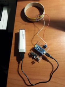
So here is how I made it.

What you’ll need:
Program the software

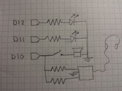
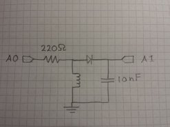
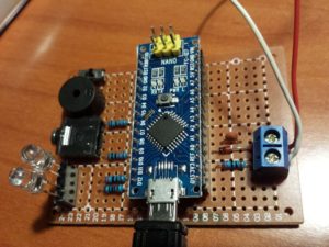
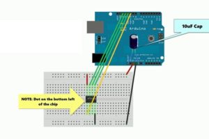
Circuit

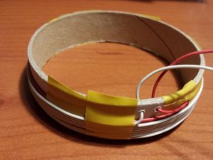
Connect the speaker

Play the sound of your cricket.
That’s all.
Thank you for reading.
Code
#include "Volume3.h"
#define speakerPin 9
void setup() {
// put your setup code here, to run once:
}
void loop() {
// put your main code here, to run repeatedly:
chirpFade();
delay(random(100,5000));
}
void chirpFade() {
uint16_t f = 3900;
uint8_t times = random(1,3);
float master = 1.0;
uint16_t v = 0;
uint8_t vDir = 1;
float vb = 0;
while (times > 0) {
while (vb < 1.0) {
if (v < 1023 && vDir == 1) {
v += 16;
}
else {
vDir = 0;
}
if (v > 0 && vDir == 0) {
v -= 16;
}
else {
vDir = 1;
}
vol.tone(speakerPin, f, v * constrain(vb, 0.0, 1.0)*master);
delayMicroseconds(50);
vb += 0.003;
}
while (vb > 0.0) {
if (v < 1023 && vDir == 1) {
v += 16;
}
else {
vDir = 0;
}
if (v > 0 && vDir == 0) {
v -= 16;
}
else {
vDir = 1;
}
vol.tone(speakerPin, f, v * constrain(vb, 0.0, 1.0)*master);
delayMicroseconds(50);
vb -= 0.001;
}
times--;
master -= 0.75;
}
vol.noTone();
}
Source
https://github.com/connornishijima/arduino-volume1/tree/master/examples/volume_crickeduino_prank