Great Tool !!! #Simulate All Your #IoT #Projects in Your Browser with #Arduino #ESP32 and #raspberrypipico https://youtu.be/FGH9u4TMf7k

Embedded systems design, Microchip PIC , Microcontroller , Electronics , Software , Computer , PC,Embedded Systems in Egypt , Microcontroller companies in Egypt , Microcontroller Tutorial for beginners, Microchip Microcontrollers tutorial , Microcontrollers made easy, Microcontroller DIY, DIY,embedded systems,embedded system , open source embedded software,list of embedded systems companies in Egypt, Quadcopter , Embedded Systems components in Egypt , Embedded Systems Components Stores in Egypt
Mturk Jobs

Mturk Jobs
Showing posts with label Arduino. Show all posts
Showing posts with label Arduino. Show all posts
Friday, December 16, 2022
Friday, May 17, 2019
How to Connect Arduino UNO to USB Keyboard - The Full Length Story
The actual sit and write is the essence of being a writer. Just as in any other discipline, if you do not invest time, mind and effort in doing it, you are treating it to be just a hobby.

The mind you give to the process of writing comes back to you in a form of the Flow. The process of effortlessly create something valuable with ease and timelessness. It’s well known that whatever habit that you devote yourself to is what you can be finally rewarded for.
That's why I've wanted to make this project to concentrate on the process of writing itself.
Today I’m showing you how I’ve made this new project. Of course, it’s about Arduino and it’s about writing.
For some reason I wanted to connect Arduino to my keyboard.
Because I love writing on the keyboard.
It’s that real physical feeling of switches on my fingertips that makes me feeling creative and alive.
But there’s only a small problem. My favorite keyboard is happened to be a USB keyboard.
Yes that’s the new modern technology is about and it’s something I should be happy with.

But the only problem I was having when I wanted to connect my keyboard to Arduino (as a host to my keyboard) I found that the standard use of Arduino with a keyboard is the PS/2 connection.
Actually there is a good well written Arduino library for this purpose.
So how could I connect my USB keyboard to Arduino? I only remembered back then when I was looking for a keyboard for my notebook (which had no PS/2 ports in it) is that I wanted to figure out some way to use a PS/2 keyboard with a USB port but I couldn’t found this.
And that’s why I bought the USB keyboard for the first place.
But this search has helped me a lot these days when I wanted to connect my USB keyboard to Arduino.
I only then remembered that although I couldn’t use a normal PS/2 keyboard with a USB port in a notebook because of the different protocol, but the opposite is doable.
I remembered that I’ve found an instructable that described building a USB to PS/2 converter.
The writer mentioned that he has tried it and it worked.
This means that you can use a modern USB keyboard with your old PCs and laptops using only this converter.
It’s just a physical converter for the connection between the keyboard and the host port(not a voltage or protocol converter). That’s because the USB keyboard can be powered from the old PS/2 port, take the CLOCK signal from it and then send DATA signal to it.
And the writer has tried to make this setup and it worked. Now it was my turn. When I looked for some information to connect a USB to an Arduino board I found that in order to do this I need either an Arduino USB shield or an Arduino board with Microcontroller that have the native USB host physical feature. Neither option were available to me.
So I’ve decided to try the physical USB to PS/2 converter - the writer has tried with his PC - between my USB keyboard and Arduino. You know what? This one also worked.
Using the PS/2 Arduino library we can connect the USB keyboard directly to Arduino boards such as Arduino UNO or Arduino Mini.


I had that female USB connector but I had to first test its pin-out with a voltmeter.
Then I made a cross connection between the USB connector and the PS/2 keyboard of the library.
USB Keyboard PS/2 Port
+5 v Vcc +5 v Vcc
Data- Data
Data+ Clock
GND GND

Components
Arduino UNO
Female USB port

Connection
USB Port Arduino
+5 v Vcc +5 v Vcc
Data- PIN 2
Data+ PIN 3
GND GND

Software
Download and save the latest Arduino PS/2 library from here.
Open Arduino IDE.
On the sketch menu, select library. Add Zip file.
Point to the Arduino PS/2 library Zip file location and then press Enter.
On the File menu select examples.
From PS2keyboard sub-menu select International.
You find the international.ino sketch loaded into the Arduino IDE.
https://github.com/PaulStoffregen/PS2Keyboard
Edit these two lines of code
#include
const int DataPin = 8 ;
const int IRQpin = 5 ;
In this case, I used
DataPin to be Arduino Pin 2
and
IRQpin to be Arduino Pin 3


Open the Serial Monitor and watch try the keyboard as you wish.

Note:
There will be a different response from some keys on the keyboard.
This is caused by difference of Arduino response to the keyboard than the standard PC.

That's why I've wanted to make this project to concentrate on the process of writing itself.
Today I’m showing you how I’ve made this new project. Of course, it’s about Arduino and it’s about writing.
For some reason I wanted to connect Arduino to my keyboard.
Because I love writing on the keyboard.
It’s that real physical feeling of switches on my fingertips that makes me feeling creative and alive.
But there’s only a small problem. My favorite keyboard is happened to be a USB keyboard.
Yes that’s the new modern technology is about and it’s something I should be happy with.
Actually there is a good well written Arduino library for this purpose.
So how could I connect my USB keyboard to Arduino? I only remembered back then when I was looking for a keyboard for my notebook (which had no PS/2 ports in it) is that I wanted to figure out some way to use a PS/2 keyboard with a USB port but I couldn’t found this.
And that’s why I bought the USB keyboard for the first place.
But this search has helped me a lot these days when I wanted to connect my USB keyboard to Arduino.
I only then remembered that although I couldn’t use a normal PS/2 keyboard with a USB port in a notebook because of the different protocol, but the opposite is doable.
I remembered that I’ve found an instructable that described building a USB to PS/2 converter.
The writer mentioned that he has tried it and it worked.
This means that you can use a modern USB keyboard with your old PCs and laptops using only this converter.
It’s just a physical converter for the connection between the keyboard and the host port(not a voltage or protocol converter). That’s because the USB keyboard can be powered from the old PS/2 port, take the CLOCK signal from it and then send DATA signal to it.
And the writer has tried to make this setup and it worked. Now it was my turn. When I looked for some information to connect a USB to an Arduino board I found that in order to do this I need either an Arduino USB shield or an Arduino board with Microcontroller that have the native USB host physical feature. Neither option were available to me.
So I’ve decided to try the physical USB to PS/2 converter - the writer has tried with his PC - between my USB keyboard and Arduino. You know what? This one also worked.
Using the PS/2 Arduino library we can connect the USB keyboard directly to Arduino boards such as Arduino UNO or Arduino Mini.


I had that female USB connector but I had to first test its pin-out with a voltmeter.
Then I made a cross connection between the USB connector and the PS/2 keyboard of the library.
USB Keyboard PS/2 Port
+5 v Vcc +5 v Vcc
Data- Data
Data+ Clock
GND GND

Components
Arduino UNO
Female USB port

USB Port Arduino
+5 v Vcc +5 v Vcc
Data- PIN 2
Data+ PIN 3
GND GND

Software
Download and save the latest Arduino PS/2 library from here.
Open Arduino IDE.
On the sketch menu, select library. Add Zip file.
Point to the Arduino PS/2 library Zip file location and then press Enter.
On the File menu select examples.
From PS2keyboard sub-menu select International.
You find the international.ino sketch loaded into the Arduino IDE.
https://github.com/PaulStoffregen/PS2Keyboard
Edit these two lines of code
#include
const int DataPin = 8 ;
const int IRQpin = 5 ;
In this case, I used
DataPin to be Arduino Pin 2
and
IRQpin to be Arduino Pin 3


Note:
There will be a different response from some keys on the keyboard.
This is caused by difference of Arduino response to the keyboard than the standard PC.
Wednesday, April 25, 2018
Arduino Capacitive Touch Sensor - How to control the world with your fingertips and an Arduino board only
We still looking in easy and affordable ways to communicate with Arduino through our bio-metric signals without having to use very expensive gadgets.
During the previous days we figured out some projects that try to read human signals (such as Galvanic Skin Response).
Today we are going to study a new project that uses human body capacitance to control Arduino projects.

In this project you’ll learn how you can control stuff connected to Arduino only by touch of your fingertips.
This is called capacitive touch sensing. You don’t need special tools or hardware. Instead, you use Arduino as a measurement tool to sense your body’s capacitance to inform Arduino board of that touch.
In this form, you can using touch as any normal control you know. This can replace a toggle stich, a push button or a slider.
You can use your imagination to control different stuff from your environment.
From my own personal experience, I’ve been noticing strange activity when interacting with microcontroller like Microchip PIC with touch. I noticed that the circuit responds to that touch. I knew then that response was a response to capacitance.
I actually thought of using touch as a means to control microcontroller. I’ve tried to make it by reading input from the microcontroller pin many times.
Although I’ve been somehow close to the right way of doing so, but I didn’t accurately read the state of touch to differentiate it from the non-touching state.
Later I found a project that implemented the idea using Microchip PIC. And today we have many projects using the Arduino capacitive touch library to make creative stuff. My dream has become true. I’m really happy about it. Even I didn’t do it myself, but my idea was correct.
And due to the fact that this circuit doesn’t require any hardware (only the Arduino board and some wires) it makes it a perfect Arduino project for me.
As you all know, I love projects that’s made of Arduino and Arduino only.
In Arduino website you can find the capacitive touch sensor library. You need to add it to your Arduino IDE and then use it in your sketches.
Source: Arduino Website , instructables


During the previous days we figured out some projects that try to read human signals (such as Galvanic Skin Response).
Today we are going to study a new project that uses human body capacitance to control Arduino projects.

This is called capacitive touch sensing. You don’t need special tools or hardware. Instead, you use Arduino as a measurement tool to sense your body’s capacitance to inform Arduino board of that touch.
In this form, you can using touch as any normal control you know. This can replace a toggle stich, a push button or a slider.
You can use your imagination to control different stuff from your environment.
From my own personal experience, I’ve been noticing strange activity when interacting with microcontroller like Microchip PIC with touch. I noticed that the circuit responds to that touch. I knew then that response was a response to capacitance.
I actually thought of using touch as a means to control microcontroller. I’ve tried to make it by reading input from the microcontroller pin many times.
Although I’ve been somehow close to the right way of doing so, but I didn’t accurately read the state of touch to differentiate it from the non-touching state.
Later I found a project that implemented the idea using Microchip PIC. And today we have many projects using the Arduino capacitive touch library to make creative stuff. My dream has become true. I’m really happy about it. Even I didn’t do it myself, but my idea was correct.
And due to the fact that this circuit doesn’t require any hardware (only the Arduino board and some wires) it makes it a perfect Arduino project for me.
As you all know, I love projects that’s made of Arduino and Arduino only.
In Arduino website you can find the capacitive touch sensor library. You need to add it to your Arduino IDE and then use it in your sketches.
Source: Arduino Website , instructables

![A Trip To Siwa Oasis: Tourist guide to an Egyptian Oasis by [ElSakhawy, Sara M.]](https://images-na.ssl-images-amazon.com/images/I/51-IGAzLKML.jpg)
![The Ultimate travel bag list by [ Elskhawy, Sara M.]](https://images-na.ssl-images-amazon.com/images/I/51OlVgqIcwL.jpg)
![Why to Travel?: Travel Like an Insider by [M., Sara]](https://images-na.ssl-images-amazon.com/images/I/51BsVhmk3ZL.jpg)
![3 Easy steps to plan your trip: Travel Like an Insider by [Elskhawy, Sara M.]](https://images-na.ssl-images-amazon.com/images/I/51GRc%2BnSxAL.jpg)
![Solar Artwork: How to Make Your Own Solar Masterpiece by [Ebeed, Ahmed]](https://images-na.ssl-images-amazon.com/images/I/51wT6i0RXNL.jpg)
![Backyard Wind Turbines: Harness wind power with simple and fun projects by [Ebeed, Ahmed]](https://images-na.ssl-images-amazon.com/images/I/51JEcdMP8JL.jpg)

Check our books on Amazon:

Learn By Making: Embedded Systems Tutorial for Students and Beginners

Embedded Systems, Electronics: My Projects Collection From Instructables
Tuesday, April 24, 2018
Arduino lie detector - How to make a simple and easy lie detector with Arduino
Yesterday we studied how to detect Galvanic Skin Response GSR with Arduino.
Today we are going to see how we can use this knowledge to build a simple Arduino based Lie detector.
I found two projects that made sense about the subject.
Actually I have a certain criteria for choosing what projects to post.
First:
There must be scientific and practical credibility for the project.
I mean that it must be real, well written and well researched.
Second:
It must be easy to build and to realize.
Easy doesn't mean with no effort. But easy means that it can be built by following the steps as stated in the project.
That's what I found in those two projects here.
First Project
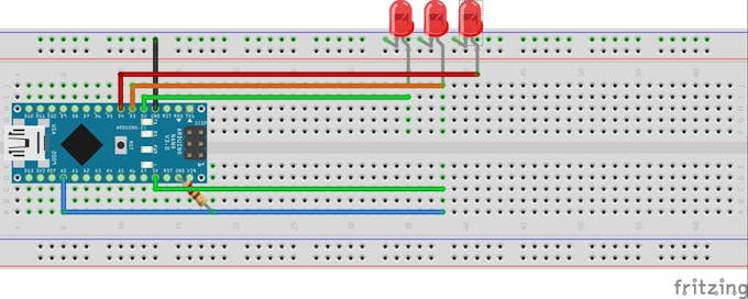
This project makes the GSR analysis with Arduino and then gives the result on one of two LEDs. Green or RED.
Circuit
Code
Second Project
This project uses temperature sensor to measure skin temperature as one of important parameters of biofeedback.
The project displays the result on an LCD and can also display results of GSR analysis on Processing code just as in yesterday project.
Circuit


Code
You can find all software for Arduino and Processing here.
Sources: Arduino Website , instructables
Check our books on Amazon:
Today we are going to see how we can use this knowledge to build a simple Arduino based Lie detector.
I found two projects that made sense about the subject.
Actually I have a certain criteria for choosing what projects to post.
First:
There must be scientific and practical credibility for the project.
I mean that it must be real, well written and well researched.
Second:
It must be easy to build and to realize.
Easy doesn't mean with no effort. But easy means that it can be built by following the steps as stated in the project.
That's what I found in those two projects here.
First Project
This project makes the GSR analysis with Arduino and then gives the result on one of two LEDs. Green or RED.
Circuit
Code
void setup()
{
 Serial.begin(9600);
 pinMode(2, OUTPUT);
 pinMode(3, OUTPUT);
 pinMode(4, OUTPUT);
 digitalWrite(2, HIGH);
 delay(500);
 digitalWrite(3, HIGH);
 delay(500);
 digitalWrite(4, HIGH);
 delay(500);
}

void loop()
{
 if (analogRead(A0) > 60)
 {
  digitalWrite(4, HIGH);
 }
 else
 {
  digitalWrite(4, LOW);
 }
 if (analogRead(A0) > 20)
 {
  digitalWrite(2, HIGH);
 }
 else
 {
  digitalWrite(2, LOW);
 }
 if (analogRead(A0) > 45)
 {
  digitalWrite(3, HIGH);
 }
 else
 {
  digitalWrite(3, LOW);
 }

 Serial.println(analogRead(A0));
 delay(20);
}
Second Project
This project uses temperature sensor to measure skin temperature as one of important parameters of biofeedback.
The project displays the result on an LCD and can also display results of GSR analysis on Processing code just as in yesterday project.
Circuit
Code
You can find all software for Arduino and Processing here.
Sources: Arduino Website , instructables
Check our books on Amazon:
Learn By Making: Embedded Systems Tutorial for Students and Beginners
Embedded Systems, Electronics: My Projects Collection From Instructables
How to make Galvanic Response Sensor with Arduino?
Today I found a Mind controlled quadcopter that is fully controlled by the power of thoughts with the NeuroSky headset and Arduino MKR1000 Board.
The project is very cool and thrilling.
It's definitely for quadcopter or Arduino haters. It actually needs a lot of work, patience and understanding.
Above all, it needs that you have the NeuroSky MindWave Headset(~$75) and MKR1000 Board(~$60) from Microsoft.
I've been searching all night about a way to make a simple and easy way to read mind signals (EKG Sensor) but without any result.
All circuits and sensors are complicated and very expensive.
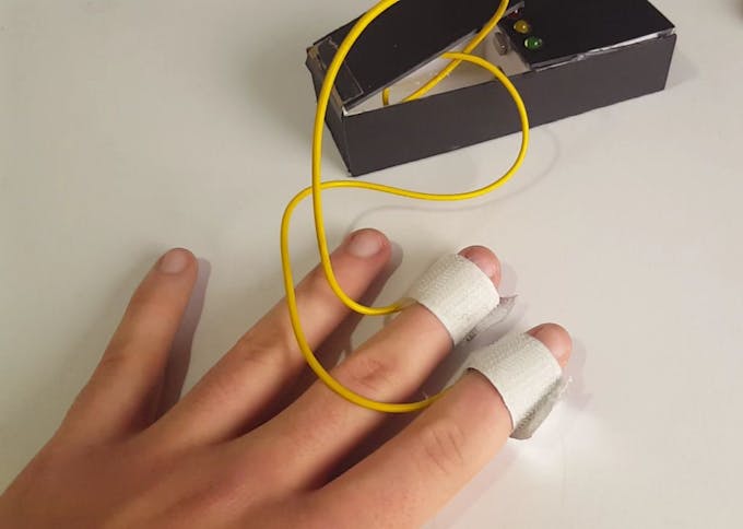
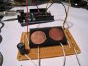
Then I just stumpled upon the GSR (Galvanic Skin Response) which is typically the skin resistance variation in different times due to stress or fear.
I found that this sensor is faily simple and easy to make.
It is actually made of two simple electrodes to measure the skin resistance without the need for any amplifiers or filters as in any other biometric signal measurement.
With one lead sends current while the other measures the difference.
Arduino is used to measure the resistance at a 50 milliseconds intervals.
The results are sent to processing code to be displayed.
That's what I call an easy project.
So I've decided to include it here on my blog.
 Code
Code
The project is very cool and thrilling.
It's definitely for quadcopter or Arduino haters. It actually needs a lot of work, patience and understanding.
Above all, it needs that you have the NeuroSky MindWave Headset(~$75) and MKR1000 Board(~$60) from Microsoft.
I've been searching all night about a way to make a simple and easy way to read mind signals (EKG Sensor) but without any result.
All circuits and sensors are complicated and very expensive.
Then I just stumpled upon the GSR (Galvanic Skin Response) which is typically the skin resistance variation in different times due to stress or fear.
I found that this sensor is faily simple and easy to make.
It is actually made of two simple electrodes to measure the skin resistance without the need for any amplifiers or filters as in any other biometric signal measurement.
With one lead sends current while the other measures the difference.
Arduino is used to measure the resistance at a 50 milliseconds intervals.
The results are sent to processing code to be displayed.
That's what I call an easy project.
So I've decided to include it here on my blog.
Arduino Code:
void setup(){
  Serial.begin(9600);
}

void loop(){
  int a=analogRead(0);
  if (Serial.available() > 0) {

    byte inbyte=Serial.read();
    if(inbyte=='a'){
      Serial.print(a,BYTE);


    }
  }
}
Processing Code:
import processing.serial.*;
Serial myPort;

int hPosition = 1;     // the horizontal position on the graph
float currentReading;
float lastReading;
int count=0;
int zeroLinePos=0;

float gsrAverage,prevGsrAverage;
float baseLine=0;
long lastFlatLine=0;
color graphColor=color(255,255,255);
int baselineTimer=10000;
int gsrValue;
int gsrZeroCount=0;
float gsrRange=0;
int downhillCount=0;
int uphillCount=0;
boolean downhill;
boolean peaked=false;
float peak, valley;

void setup () {
  size(900, 450);
  // List all the available serial ports
  //println(Serial.list());

  myPort = new Serial(this, Serial.list()[0], 9600);
  currentReading=0;
  lastReading=0;
  gsrAverage=0;
  background(0);

  smooth();
}

void draw () {
  //best delay setting for gsr readings
  delay(50);
  //image(myMovie, 0, 0);

  if (gsrValue<15 amp="" gsrvalue="">-15){
    if( gsrZeroCount>10){
      currentReading=0;//flatline
      gsrAverage=0;
      baseLine=0;
      lastFlatLine=millis();
      gsrZeroCount=0;
      // println("reset");

    }
    gsrZeroCount++;
  }
  else{
    currentReading=gsrValue-baseLine;
    gsrZeroCount=0;
  }

  if(millis()-lastFlatLine>baselineTimer){
    baseLine=gsrAverage;
  }

  //graph colors
  if(gsrAverage>0 && gsrAverageheight/2.0*.25 && gsrAverageheight/2.0*.5 && gsrAverageheight/2.0*.75) graphColor=color(255,100,0);

  gsrRange=peak-valley;

  // at the edge of the screen, go back to the beginning:
  if (hPosition >= width) {
    hPosition = 0;

    //cover last drawing
    fill(0,200);
    noStroke();
    rect(0,0,width,height);
  }
  else {
    hPosition+=1;
  }

  gsrAverage=smooth(currentReading,.97,gsrAverage);

  //draw stuff

  //spike
  noStroke();
  if(gsrRange>200){
    fill(255);
    ellipse(10,10,20,20);
  }
  else{
    fill(0);
    ellipse(10,10,20,20);
  }

  //graph
  strokeWeight(.5);
  stroke(graphColor);
  line(hPosition-1, height/2.0-lastReading, hPosition, height/2.0-currentReading);
  stroke(255,0,100);
  line(hPosition-1,height/2.0-prevGsrAverage,hPosition,height/2.0-gsrAverage);

  //draw peaks
  int thres=7;

  noFill();
  stroke(255,0,0);
  strokeWeight(2);

  if (currentReading-thres>lastReading&& peaked==true){
    downhill=false;
    //println(downhillCount);
    uphillCount++;
    downhillCount=0;
    point(hPosition-1, height/2.0-lastReading);
    valley=lastReading;
    peaked=false;

  }
  if(currentReading+thres 1){      // check to make sure param's are within range
    filterVal = .99;
  }
  else if (filterVal <= 0){
    filterVal = 0;
  }
  smoothedVal = (data * (1 - filterVal)) + (smoothedVal  *  filterVal);
  return (int)smoothedVal;
} Saturday, April 21, 2018
Arduino KiTT From KnightRider - AKA Larson Scanner
In this quick example, we'll see how to make a beautiful Larson Scanner as in the TV show Knight Rider.
Circuit
You can make it any number of LEDs you like. Here is the code that moves 6 LEDs in sequence.
This project is called LED chaser or Larson Scanner


Code
Circuit
You can make it any number of LEDs you like. Here is the code that moves 6 LEDs in sequence.
This project is called LED chaser or Larson Scanner
Code
/* Knight Rider 3
 * --------------
 *
 * This example concentrates on making the visuals fluid.
 *
 *
 * (cleft) 2005 K3, Malmo University
 * @author: David Cuartielles
 * @hardware: David Cuartielles, Aaron Hallborg
 */

int pinArray[] = {2, 3, 4, 5, 6, 7};
int count = 0;
int timer = 30;

void setup(){
  for (count=0;count<6 1="" count="5;count" delay="" digitalwrite="" for="" high="" loop="" low="" output="" pinarray="" pinmode="" timer="" void="">0;count--) {
   digitalWrite(pinArray[count], HIGH);
   delay(timer);
   digitalWrite(pinArray[count - 1], HIGH);
   delay(timer);
   digitalWrite(pinArray[count], LOW);
   delay(timer*2);
  }
}
This is the Larson scanner effect that was presented in the famous knight rider series in the 80's.
It featured a smart autonomous car that had a talking on-board computer.
I'd like to mention that this project was one of my first things to make when I started to learn embedded systems using PIC16F84A microcontroller.


I made this project and posted it in Arabic and English languages. I didn't post a video for it but I still have the circuit.
http://arabic-embedded-egypt.blogspot.com.eg/2010/05/led-chaser.html
http://embedded-egypt.blogspot.com.eg/2009/06/led-chaser-larson-scanner.html
So I'll post a video soon.
Source: Arduino Website , instructables
It featured a smart autonomous car that had a talking on-board computer.

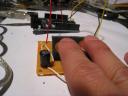
Here is my actual circuit
This is Proteus simulation of the circuit
I made this project and posted it in Arabic and English languages. I didn't post a video for it but I still have the circuit.
http://arabic-embedded-egypt.blogspot.com.eg/2010/05/led-chaser.html
http://embedded-egypt.blogspot.com.eg/2009/06/led-chaser-larson-scanner.html
So I'll post a video soon.
Source: Arduino Website , instructables
Subscribe to:
Posts (Atom)